wasserwiesel
Well-known member
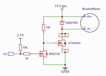
Since no one can or like to explain to me if my schematic will work or not and I still like the simplicity, I will give it a try and will order the pcb like this... 

Are these schematics better? If yes, which one? I long for knowledge 

Are these schematics better?


The SimpleFoc lib works with 3 pwm pins for driving 3 phase brushless (BLDC). Would it still make sense to aim for the eFlexPWM or would the Quadtimer be better at that ?
#ifndef IMXRT_FLEXPWM4
#error Needs Teensy 4.x, or compatible i.MXRT1062 board.
#endif

#define DEADTIME    3  // in half cycles (PWM clocked at 150MHz normally), so 3 = 24 cycles = 170ns
#define MIN_PWM    -444 // with the 115% PWM trick this permits upto 512 amplitude
#define MAX_PWM    +444
#define MID_PWM    (MAX_PWM + 2 * DEADTIME)
#define HALFCYCLE  (2 * MAX_PWM + 4 * DEADTIME)
#define TWOTO32    (65536.0 * 65536.0)  // 2^32
#define MAX_AMPLITUDE 512

// The i.MXRT1062 uses one config register per two XBAR outputs, so a helper
// function to make code more readable.
bool xbar_connect (uint8_t input, uint8_t output)
{
  if (input >= 88 || output >= 132)
    return false;
  volatile uint16_t * xbar_select_reg = &XBARA1_SEL0 + (output >> 1); // 1 reg per 2 outputs
  if (output & 1)  // high byte or low byte choice.
    *xbar_select_reg = (*xbar_select_reg & 0x00FF) | (input << 8);
  else
    *xbar_select_reg = (*xbar_select_reg & 0xFF00) | input;
  return true;
}

/* 3-phase PWM with deadtime
 *
 *
 * Three A/B FlexPWM pairs, Teensy 4.x pins 2/3 (U-channel) and 6/9 (V-channel) and 8/7 (W-channel)
 *
 */

IMXRT_FLEXPWM_t * flexpwm23 = &IMXRT_FLEXPWM4 ;
#define submodule23  2
IMXRT_FLEXPWM_t * flexpwm87 = &IMXRT_FLEXPWM1 ;
#define submodule87  3
IMXRT_FLEXPWM_t * flexpwm69 = &IMXRT_FLEXPWM2 ;
#define submodule69  2


// Helper to set up A/B pair on a FlexPWM submodule.
// can configure sync, prescale and B inversion.
void setup_pwm_pair (IMXRT_FLEXPWM_t * flexpwm, int submodule, bool ext_sync, int prescaler, bool invert_B)
{
  int submodule_mask = 1 << submodule ;
  flexpwm->MCTRL &= ~ FLEXPWM_MCTRL_RUN (submodule_mask) ;  // stop it if its already running
  flexpwm->MCTRL |= FLEXPWM_MCTRL_CLDOK (submodule_mask) ;  // clear load OK

  int sel = ext_sync ? 3 : 0;
  flexpwm->SM[submodule].CTRL2 = FLEXPWM_SMCTRL2_INDEP | FLEXPWM_SMCTRL2_WAITEN | FLEXPWM_SMCTRL2_DBGEN |
                                 FLEXPWM_SMCTRL2_FRCEN | FLEXPWM_SMCTRL2_INIT_SEL(sel) | FLEXPWM_SMCTRL2_FORCE_SEL(6) ;
  flexpwm->SM[submodule].CTRL  = FLEXPWM_SMCTRL_FULL | FLEXPWM_SMCTRL_HALF | FLEXPWM_SMCTRL_PRSC(prescaler) ;
  flexpwm->SM[submodule].OCTRL = invert_B ? FLEXPWM_SMOCTRL_POLB : 0 ;
  flexpwm->SM[submodule].DTCNT0 = 0 ;  // should try this out (deadtime control)
  flexpwm->SM[submodule].TCTRL = FLEXPWM_SMTCTRL_OUT_TRIG_EN (0b000010)  ; // sync trig out on VAL1 match.
  flexpwm->SM[submodule].INIT = -HALFCYCLE ;      // count from -HALFCYCLE to +HALFCYCLE
  flexpwm->SM[submodule].VAL0 = 0 ;
  flexpwm->SM[submodule].VAL1 = HALFCYCLE ;
  flexpwm->SM[submodule].VAL2 = -MID_PWM + DEADTIME ;
  flexpwm->SM[submodule].VAL3 = +MID_PWM - DEADTIME ;
  flexpwm->SM[submodule].VAL4 = -MID_PWM - DEADTIME ;
  flexpwm->SM[submodule].VAL5 = +MID_PWM + DEADTIME ;

  flexpwm->MCTRL |= FLEXPWM_MCTRL_LDOK (submodule_mask) ;  // loading reenabled
  flexpwm->MCTRL |= FLEXPWM_MCTRL_RUN (submodule_mask) ;   // start it running
}

void startup_pwm_pair (IMXRT_FLEXPWM_t * flexpwm, int submodule)
{
  int submodule_mask = 1 << submodule ;

  flexpwm->OUTEN |= FLEXPWM_OUTEN_PWMA_EN (submodule_mask); // enable A output
  flexpwm->OUTEN |= FLEXPWM_OUTEN_PWMB_EN (submodule_mask); // enable B output
}


volatile static uint32_t time0 = 0 ;   // store cycle count ARM_DWT_CYCCNT here when record phase
volatile static float freq = 0.0 ;     // used to advance the phase whenever its accessed by update_phase
volatile static uint32_t phase = 0.0 ;  // signed integer phase, MININT--MAXINT represents -pi to +pi.

void set_freq (float f)
{
  uint32_t now = ARM_DWT_CYCCNT ;  // reference timestamp for freq change
  uint64_t ph = phase ;
  int64_t inc = (int64_t) (freq * long(now - time0)) ;  // allow signed phase exceeding +/-pi range
  inc += ph ;
  ph = (uint32_t) (inc & 0xffffffffL) ;

  noInterrupts() ;   // critical section to update time0, phase and freq atomically
  time0 = now ;
  phase = ph ;
  freq = f ;
  interrupts() ;
}

// read the current phase, allowing for current value of freq, re-store it updated with new timestamp
inline uint32_t update_phase (void)
{
  uint32_t now = ARM_DWT_CYCCNT ;  // reference timestamp for freq change
  uint64_t ph = phase ;
  int64_t inc = (int64_t) (freq * long(now - time0)) ;  // allow signed phase exceeding +/-pi range
  inc += ph ;
  ph = (uint32_t) (inc & 0xffffffffL) ;

  //noInterrupts() ;   // critical section to update time0 and phase atomically
  time0 = now ;
  phase = ph ;
  //interrupts() ;

  return ph ;
}

void init_phase (float frequency)
{
  time0 = ARM_DWT_CYCCNT ;
  set_freq (TWOTO32 * frequency / 6e8) ;
}

// helpers
inline int max3 (int a, int b, int c)
{
  if (b > a) a = b ;
  if (c > a) a = c ;
  return a ;
}
inline int min3 (int a, int b, int c)
{
  if (b < a) a = b ;
  if (c < a) a = c ;
  return a ;
}


volatile static float amplitude = 0.0 ;

void pwm_handler (void)
{
  FLEXPWM4_SM2STS |= FLEXPWM_SMSTS_RF; // Clear Reload

  // Use pin 1 for 'scope trigger.
  static volatile byte pin1_val = 0 ;
  digitalWrite (1, pin1_val) ;
  pin1_val = 1-pin1_val ;

  int32_t intph = update_phase() ;
  // could improve this to use lookup rather than transcendental function calls
  float ph = 2*M_PI * intph / TWOTO32 ;
  int Uactual = int(amplitude * sin (ph)) ;
  int Vactual = int(amplitude * sin (ph+M_PI*2/3)) ;
  int Wactual = -(Uactual+Vactual) ;

  // Hack to allow 15% higher amplitude by shifting the phase triangle to the midpoint of its max and min values
  int midpoint = MID_PWM - (max3 (Uactual, Vactual, Wactual) +
                            min3 (Uactual, Vactual, Wactual)) / 2 ;
  // PWM requires swing between 0 and HALF_CYCLE, midpoint shifts the signed values up
  Uactual += midpoint ;
  Vactual += midpoint ;
  Wactual += midpoint ;

  // using phase-correct PWM with updates for half point as well as full for lowest latency
  // future work - figure out using the inbuilt deadtime options
  // U channel
  flexpwm23->SM[submodule23].VAL2 = -Uactual + DEADTIME ; // A on
  flexpwm23->SM[submodule23].VAL3 = +Uactual - DEADTIME ; // A off
  flexpwm23->SM[submodule23].VAL4 = -Uactual - DEADTIME ; // B off  (assuming B inverted)
  flexpwm23->SM[submodule23].VAL5 = +Uactual + DEADTIME ; // B on
  flexpwm23->MCTRL |= FLEXPWM_MCTRL_LDOK (1<<submodule23) ;  // signal new values
  // V channel
  flexpwm69->SM[submodule69].VAL2 = -Vactual + DEADTIME ;
  flexpwm69->SM[submodule69].VAL3 = +Vactual - DEADTIME ;
  flexpwm69->SM[submodule69].VAL4 = -Vactual - DEADTIME ;
  flexpwm69->SM[submodule69].VAL5 = +Vactual + DEADTIME ;
  flexpwm69->MCTRL |= FLEXPWM_MCTRL_LDOK (1<<submodule69) ;
  // W channel
  flexpwm87->SM[submodule87].VAL2 = -Wactual + DEADTIME ;
  flexpwm87->SM[submodule87].VAL3 = +Wactual - DEADTIME ;
  flexpwm87->SM[submodule87].VAL4 = -Wactual - DEADTIME ;
  flexpwm87->SM[submodule87].VAL5 = +Wactual + DEADTIME ;
  flexpwm87->MCTRL |= FLEXPWM_MCTRL_LDOK (1<<submodule87) ;

  digitalWrite (1, LOW) ;
  asm("dsb":::"memory");
 }


float frequency = 0.0;

void setup(void)
{
  Serial.begin (115200) ;
  // ensure pins inactive
  pinMode (2, INPUT) ;
  pinMode (3, INPUT) ;
  pinMode (6, INPUT) ;
  pinMode (7, INPUT) ;
  pinMode (8, INPUT) ;
  pinMode (9, INPUT) ;
  // pins used for 'scope observation.
  pinMode (1, OUTPUT) ;
  pinMode (4, OUTPUT) ;

  delay(20) ;


  // Configure FlexPWM units, each driving A/B pair, B inverted.
  // full speed about 80kHz, prescale 2 (div by 4) gives 20kHz
  setup_pwm_pair (flexpwm23, submodule23, false, 2, true) ;  // this is the master, internally synced
  //delayMicroseconds (5) ;
  setup_pwm_pair (flexpwm69, submodule69, true, 2, true) ;   // others externally synced
  //delayMicroseconds (5) ;
  setup_pwm_pair (flexpwm87, submodule87, true, 2, true) ;
  delayMicroseconds (100) ;

  // turn on XBAR1 clock for all but stop mode
  CCM_CCGR2 |= CCM_CCGR2_XBAR1(3);

  // Connect trigger to synchronize all three units
  xbar_connect (XBARA1_IN_FLEXPWM4_PWM3_OUT_TRIG0, XBARA1_OUT_FLEXPWM1_PWM3_EXT_SYNC) ;
  xbar_connect (XBARA1_IN_FLEXPWM4_PWM3_OUT_TRIG0, XBARA1_OUT_FLEXPWM2_PWM2_EXT_SYNC) ;


  startup_pwm_pair (flexpwm23, submodule23) ;
  startup_pwm_pair (flexpwm69, submodule69) ;
  startup_pwm_pair (flexpwm87, submodule87) ;

  init_phase (frequency) ;

  delayMicroseconds(50) ;
  // config the pins 2/3/6/9/8/7 as their FLEXPWM alternates.
  CORE_PIN2_CONFIG = 1 ; // pwm_pin_info[2].muxval ;
  CORE_PIN3_CONFIG = 1 ; // pwm_pin_info[3].muxval ;

  CORE_PIN6_CONFIG = 2 ; // pwm_pin_info[6].muxval ;
  CORE_PIN9_CONFIG = 2 ; // pwm_pin_info[9].muxval ;

  CORE_PIN8_CONFIG = 6 ; // pwm_pin_info[8].muxval ;
  CORE_PIN7_CONFIG = 6 ; // pwm_pin_info[7].muxval ;

   // pin 4 observes out trigger line for 'scope
  xbar_connect (XBARA1_IN_FLEXPWM4_PWM3_OUT_TRIG0, XBARA1_OUT_IOMUX_XBAR_INOUT08) ;
  IOMUXC_GPR_GPR6 |= IOMUXC_GPR_GPR6_IOMUXC_XBAR_DIR_SEL_8 ;  // select output mode for INOUT8
  // Select alt 3 for  EMC_06 (XBAR), rather than original 5 (GPIO)
  CORE_PIN4_CONFIG = 3 ; // shorthand for  IOMUXC_SW_MUX_CTL_PAD_GPIO_EMC_06 =  3 ;
  // turn up drive & speed as very short pulse
  IOMUXC_SW_PAD_CTL_PAD_GPIO_EMC_06 = IOMUXC_PAD_DSE(7) | IOMUXC_PAD_SPEED(3) | IOMUXC_PAD_SRE ;

  //amplitude = MAX_AMPLITUDE * 0.8;

  //delay(4000);
  // Configure FlexPWM4 SM2 interrupt on reload
  attachInterruptVector (IRQ_FLEXPWM4_2, pwm_handler);
  NVIC_ENABLE_IRQ (IRQ_FLEXPWM4_2);
  FLEXPWM4_SM2INTEN |= FLEXPWM_SMINTEN_RIE ; // Reload Interrupt Enable
}

float frequency_inc = 0.08 ; //0.000002 ;

void loop ()
{
  set_freq (TWOTO32 * frequency / 6e8) ;
  // If I got things right frequency is in units of Hz if running at 600MHz

  // play with frequency and amplitude to show off waveforms on 'scope.
  frequency = constrain (frequency + frequency_inc, -300.0, 300.0) ;
  if (frequency == 300.0)
    frequency = -300.0 ;
  amplitude = constrain (amplitude + 0.04, 0.0, MAX_AMPLITUDE) ;
  //if (amplitude == MAX_AMPLITUDE)
   // amplitude = 0.0 ;
  delay (1) ;
}
/* 3-phase PWM with deadtime
*
*
* Three A/B FlexPWM pairs, Teensy 4.x pins 2/3 (U-channel) and 6/9 (V-channel) and 8/7 (W-channel)
*
*/