Yes, for 20 kHz PWM, you probably do need a gate driver chip or circuit.
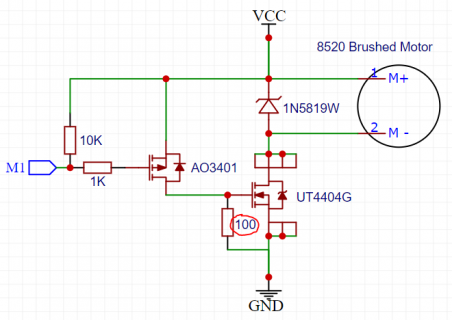
You should also use a "fast" diode across the motor. IN4007 is very slow. Without a good quality diode or other snubber circuit, the motor's "back EMF" will create voltage spikes which stress or even destroy the mosfet. Use a good diode!
Computing actual gate voltage waveforms involves way to much non-linear math (at least for me). Better to use a simple approximation and then design in a little extra margin.
The main mosfet spec to consider is the "total gate charge", which sort of packages up all the complexity of a mosfet into 1 simple number that's actually useful for circuit design. I'm not familiar with this transistor, but quick google search turned up a datasheet which says 10nC typical and 12nC worst case. If those numbers aren't accurate for the part you're using, hopefully this explanation will at least help show how to estimate this sort of thing.
The other key piece of info is an idea of how slowly you're willing to tolerate the transistor switching. This number is really matter of your personal preference or performance requirement. I'm going to just guess 1% of the PWM period, which is 500ns for 20 kHz PWM.
If you use some imagination that your gate driving circuit will deliver constant current, then just divide these numbers to get the current required to make the gate change in that amount of time, because the electrical current (amperes) is coulombs per second. So for this case, 10nC divided by 500ns means you need 20mA.
Of course driving the gate with a fixed voltage through a series resistor isn't going to give constant current. But 3.3V and 1K definitely isn't going to be fast enough, since the current starts at 3.3mA and decreases as you go, which falls pretty far short of the constant 20mA goal.
Again, you could put a lot of work into non-linear math, but I usually prefer to just do a simpler estimate. Usually I look for the lowest gate voltage the transistor datasheet gives an on resistance spec, which is 2.5V in the datasheet I found. I just assume if the transistor actually works reasonable well at lower voltage, the marketing folks who wrote the datasheet would have mentioned it (remember, datasheets are a sales pitch). So I would compute the actual current through the resistor when the mosfet is at this minimum performance point. That means 0.8V across the resistor when the mosfet is just reaching a reasonably good on state. If you choose the parts for the right current at that point, you can know you drove more current before the mosfet got to this minimum performance, and then less to go from that point to the gate fully charged.
So if you want 20mA current when you have only 0.8V, then you would need a 40 ohm resistor. That's too low for Teensy to drive directly. You could add a buffer chip. If you use a chip which drives with more than 3.3V, then the required resistor changes. If you drive 5V, then you would have 2.5V at the mosfet-just-turned-on point. For 20mA, you could use 125 ohms, rather than only 40.
This is all very approximate, but hopefully it gives you a way to estimate without diving down a difficult and error-prone rabbit hole of non-linear math.


") Nice, I didn't expect an answer from the Mastermid right away. Thank you very much for your time.
Nice, I didn't expect an answer from the Mastermid right away. Thank you very much for your time.