Shrink the TinyPICO

FRDM4236

Active member
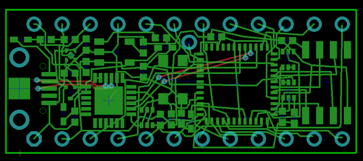
After several version changes, I placed all components on the size of my Mini-T3.2. Top layer only, including the PSRAM. The CH340G has no DTR signal, so I have to use the CP2104.
For a good reason I extended the PCB 1.27mm longer, but the length of the PCB is still no longer than the TinyPICO.
I made two hardware improvements on TinyPICO to reduce battery consumption, I use electronic circuits instead of jumper cutting on the PCB underside. There is no reason why the battery charge status orange LED needs to blink when no battery is connected, that's a bit annoying. I will look into it and hope a solution can be found. I ditched the Ant. on the TinyPICO, instead I use a whip Ant. to make more room available for the final layout. The test result of the whip Ant. was good.
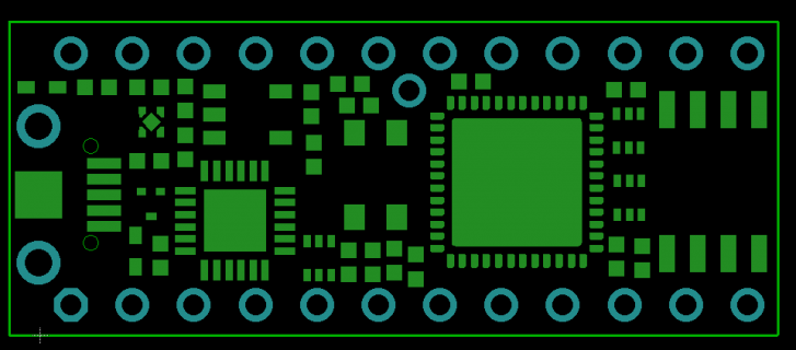
a_smaller_tinypico.png

Can I do it? The short answer is yes, but the long answer is that I will struggle. It will take longer than I expected. The last few PCB routings will take hours if not days. The worst case is to change some parts from 0402 to 0201, or make it a 4-layer PCB like the TinyPCB. The holidays are coming and I have been on office moving. I may not be able to finish the prototype this month as I planned.

For hand Pick and Place, I will avoid 0201 as much as possible. The soldering is not an issue, but the handling is. It's so tiny and gets stuck on my tweezer easily, I cannot even shake it off. It's very hard to manually place it on a PCB. If anyone has a better solution please kindly share it.
 
Last edited by a moderator:
Interesting and nice work. And having built and tested one to work is great!

Could the PSRAM be bottom mounted ( 8 pads on right end of image? ) - still need to route those signals - but that could yield a lot of top side space for the 0402's to be used.

Flashing battery charge lights are very annoying, good luck with that.

I suppose that is the whip Ant hole center top of that image inside the edge pin row at the corner of the MCU? OneHorse had decent results with whip antennas. Seems it may give more options for mounting

Not sure where battery connects? Don't see typical JST pin holes?
 
Thanks defragster for your suggestions.

The JST battery connector can be added later, I am thinking about all options.
The PSRAM will be on the top, I will try to use 0402 as many as possible, at least all capacitors will be 0402.
The whip Ant. is just a 1.17" hook up wire. A commercial whip Ant. basically is a wire, the wire is $0.10, they add a nice case and sell you for $10, what a deal? Of cause a police 's walkie talkie cannot use a wire, looks too cheap, but for a hobby project, a wire should be acceptable especially it will save $2. I tested it on the TinyPICO. The result is good, as good as the fancy 3D Ant.

My circuit design is done. BOM is done. All traces are connected. Those traces need to be cleaned up. It's pretty messy now.

wires.png

I already started to lay out the PCB. Looks like I may be able to get the prototype PCB assembled this month or the 1st week of January. I want to stop the orange LED flickering. I think it can be fixed, my design works on the paper and I hope it will work on my prototype. The prototype will catch all of my mistakes, then the final board can be made in a month.

The RGB LED is a very nice feature, unfortunately it requires 3 more I/O pins to control it. Adding 3 more connections is too difficult for the PCB layout on this tiny board. I will ditch that too
 
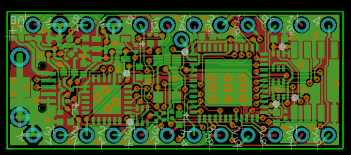
My PCB layout is done. I hope that I can get an assembled board in two weeks. Someone is going to assemble it for me.

pcb.png

The board is denser than my Mini_T32 board, it should take longer to finish, but it was easier than I thought, maybe because I moved down from 6mil/6mil trace and 12mil/24mil hole to 5mil/5/mil trace and 10mil/20mil hole. It gave me more space to play around.

I had to change 5 resistors from 0402 to 0201 to complete the layout.

The 0201 is harder to handle, but I found a new tool to overcome this problem, I hope other makers find it useful.
The tool is a cross locking tweezer. Once you pick up a 0201, the tweezer will lock on the 0201, you don't have to worry losing it. How many times did you lose a 0201 with a regular tweezer? I lost quite a few.
Once one side of a 0201 is soldered to the pad, you can unlock the 0201, then solder the other side. This tool can also help on other sizes, 0402 or 0603.

i think that I may have a good luck of stopping the orange LED flashing on the T1nyPICO. See the potential solution.
 
Last edited:
Interesting - and the parts to build it are available? Nice if the RC circuit can mute the annoying flash from the charge circuit when not charging.
Hope the test builds work on the first try.
 
I sent out the Gerber files on 12/13, the PCB house has not started making it until today. If they don't start it, I will not have a delivery date. Everyday I asked them to start rolling the ball, but nothing happened, my order was just sitting there. I changed the board color from black to green to help them speed up. Now I just need to wait. I think that they will be able to ship before Christmas and I will receive it in the last week of this month.

The Parts shortage is another problem, I spent more time to hunt parts ( for my other products too) than laying the PCB. The assembly service will not have a SOT-563 part, and they cannot install 0201 resistors, I just bought all parts needed and will install them by myself. Since I can use a cross locking tweezer, installing 0201 resistors will not be a problem any more. The CP2104 is too expensive, I had to pay $4.5 each, unbelievable! The TinyPICO-S2 does not need it, maybe I should make that one. It should be a bit easier because it has more space without two large parts, CP2104 and the PSRAM.

Without all parts fully installed, It may not work except checking the orange LED flickering problem. I will let you know the test result as soon as I receive the board.

I don't remember if I ever had my prototype work on the first try. I always need to fix something after the first try.
 
That doesn't sound fun or easy - $4.50 for the USB part. AdaF has a few of the single core S2 boards. I saw there is an S3 with BLE LE and 2 cores with WiFi.
 
Saw the LED flicker thread updated. How goes the rest of the board assembly? Is it with the single core S2 already? Or the costly dual core needing the CP2104?
 
Before I tested the LPF I just plugged the board in a USB port to check it out. It looked OK and nothing was burning my finger. After added a through hole resistor and a cap on the reset pin I uploaded the Blink-A-LED sketches OK, fast and just like the TinyPICO. I got the following message,
Leaving...
Hard resetting via RTS pin..,

but the code did not run. I tried a few different I/O pins, no waveform could be seen. I stopped there and tested the LPF first.

Today I will troubleshoot it. A PCB design error is known. I had a typo in a signal name and the result is that the pin 5 of the PSRAM is not connected to the PICO-D4 chip. That proved that I always need a second try or more.

I am pretty much sure that this board will work, a very straight forward circuit, nothing is special. I will let you know this week.

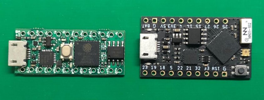
size_comparison.jpg

The bigger button is like the one on the Teensy board. it's bigger, but I like the feeling when it's pushed. The footprint of the CP2104 is too big. It can be smaller and save some space. Every bit of saving counts for a 2-layer board.

I have not started a S2 board. The CP2104 may be replaced by a FT231XQ if the price difference is big.
 
Last edited:
After some troubleshooting I found the cause why it did not run the Blink-A-LED.

The PSRAM was not working because one pin was not connected to the PICO-D4.

When the PSRAM is not working, the TinyPICO will stay in a loop to test it continuously, so it won't execute a user's sketch. I found it from the serial monitor output.

In order to run my sketch, I changed the board type from TinyPico to ESP32-Pico-Kit. The Blink-A-LED worked like a charm. See the video clip: https://firebird32.com/fb32_1.mov

The ESP32-Pico-Kit is the gold standard. All Pico-D4 boards are basically its offspring. My small board actually is closer to the official ESP32-Pico-Kit than to the TinyPICO. A sketch running on the ESP32-Pico-Kit will run on this small board without modification if it uses I/O pins available on this small board.

I will name this small board TTPico. I will be making the TTPico-V2 this week. It will include all the fixes. Hopefully it will have no 0201. It will be easier for assembly houses.
After the TTPico-V2 is released for the 2nd prototype, I will test it with SPI TFT display and I2C OLED display. Hopefully they will work too.

BTW, I tested my whip ANT. on the TTPico, it worked great. The result is better than the fancy 3D ANT. It picked up more WiFi sites on the same location than a fancy 3D ANT.
 
Back
Top