OCTOWS2811 - 16 outs

MikkelM

Member
Hi There.

I am trying to get 16 lines of LED to work on a Teensy, but I have problems with pin 1 which flickers and 6 + 7, which makes tivoli lights.

Code:
#define NUM_OF_OUTPUTS 16
#define MAX_NUM_LED_PER_OUTPUT 216
#define NUM_CHANNEL_PER_LED 4 // do not change this

const int num_channel_per_output = MAX_NUM_LED_PER_OUTPUT * NUM_CHANNEL_PER_LED;
const int num_universes_per_output = (num_channel_per_output%512) ? num_channel_per_output/512+1 : num_channel_per_output/512;
const int num_led_per_output = num_universes_per_output*512/NUM_CHANNEL_PER_LED;

#include <OctoWS2811.h>

DMAMEM uint32_t displayMemory[num_led_per_output * NUM_OF_OUTPUTS];
uint32_t drawingMemory[num_led_per_output *  NUM_OF_OUTPUTS];
uint8_t pinList[16] = {0, 1, 2, 3, 4, 5, 6, 7, 8, 9, 14, 15, 18, 19, 22, 23}; //PIN 1 flicker,6 and 7 Tivoli light

const int LEDconfig = WS2811_RGBW | WS2811_800kHz;

OctoWS2811 LEDS(num_led_per_output, displayMemory, drawingMemory, LEDconfig, NUM_OF_OUTPUTS, pinList);

void setup() {
   LEDS.begin();
}

void loop() {
  uint8_t val = map(sin(millis()/100), -1.0, 1.0, 0x00, 0xFF);
  for (int i = 0; i < NUM_OF_OUTPUTS * num_led_per_output; i++) {//CHANGE
    LEDS.setPixel(i, val, val, val, val);
  }
  LEDS.show();
}
 
Glad you found the problem.

I had saved a bookmark to later investigate this issue. Sounds like 16 outputs works (and I don't need to set up a hardware test).
 
16 output works, but I am having trouble with ground and cable length when I drive 16 LED strips.
I have an ground offset and high capacity, which interrupts the falling edge of the data pulse. The pulse gets too long.
It seems like I could get rid of my glitching issues if I make the pulse time shorter, are anybody able to guide me where to do that as the DMA is above my level of programming.

Cheers
 
I don't understand how changing the pulse timing is going to compensate for an electrical problem like insufficient ground.

But if you really want to try, look for these lines in OctoWS2811_imxrt.cpp

Code:
#define TH_TL   1.25e-6
#define T0H     0.30e-6
#define T1H     0.75e-6

These are the WS2812 waveform timing parameters, with the same naming convention as typically shown in the datasheet.

If you want to make the low pulse shorter than the normal 300ns, just change 0.30e-6 to whatever number you like. Well, within reason, as the timer hardware doesn't have a huge range it can create, and ultimately it's running from the 150 MHz peripheral clock, so the resolution to timing changes is about 6.7ns.
 
I have Problems with getting the right color to the right led with this code, and I don't know why. In this example code just 7 of my 12 WS2812b strips are showing the program, but if I give all strips the same color or color pattern, the pattern is shown correctly.

(Sorry for my bad English)

Code:
#define NUM_OF_OUTPUTS 12
#define MAX_NUM_LED_PER_OUTPUT 50
#define NUM_CHANNEL_PER_LED 4 // do not change this

const int num_channel_per_output = MAX_NUM_LED_PER_OUTPUT * NUM_CHANNEL_PER_LED;
const int num_universes_per_output = (num_channel_per_output%512) ? num_channel_per_output/512+1 : num_channel_per_output/512;
const int num_led_per_output = num_universes_per_output*512/NUM_CHANNEL_PER_LED;

#include <OctoWS2811.h>

DMAMEM uint32_t displayMemory[num_led_per_output * NUM_OF_OUTPUTS];
uint32_t drawingMemory[num_led_per_output *  NUM_OF_OUTPUTS];
uint8_t pinList[12] = {0, 1, 3, 4, 5, 6, 7, 8, 9, 10, 11, 12}; //PIN 1 flicker,6 and 7 Tivoli light

const int LEDconfig = WS2811_GRB | WS2811_800kHz;

OctoWS2811 LEDS(num_led_per_output, displayMemory, drawingMemory, LEDconfig, NUM_OF_OUTPUTS, pinList);

void setup() {
   LEDS.begin();
}

void loop() {
  //uint8_t val = map(sin(millis()/1000), -1.0, 1.0, 0x00, 0xFF);
  //for (int i = 0; i < NUM_OF_OUTPUTS * num_led_per_output; i++) {
  for (int i = 0; i < num_led_per_output; i++) {//CHANGE
    //LEDS.setPixel(i, val, val, val, val);
    LEDS.setPixel(i, 20, 20, 0);
    LEDS.setPixel(i+50, 20, 20, 0);
    LEDS.setPixel(i+100, 20, 20, 0);
    LEDS.setPixel(i+150, 20, 20, 0);
    LEDS.setPixel(i+200, 20, 20, 0);
    LEDS.setPixel(i+250, 20, 20, 0);
    LEDS.setPixel(i+300, 20, 20, 0);
    LEDS.setPixel(i+350, 20, 20, 0);
    LEDS.setPixel(i+400, 20, 20, 0);
    LEDS.setPixel(i+450, 20, 20, 0);
    LEDS.setPixel(i+500, 20, 20, 0);
    LEDS.setPixel(i+550, 20, 20, 0);
    LEDS.show();
    delay(20);
    LEDS.setPixel(i, 0, 0, 0);
    LEDS.setPixel(i+50, 0, 0, 0);
    LEDS.setPixel(i+100, 0, 0, 0);
    LEDS.setPixel(i+150, 0, 0, 0);
    LEDS.setPixel(i+200, 0, 0, 0);
    LEDS.setPixel(i+250, 0, 0, 0);
    LEDS.setPixel(i+300, 0, 0, 0);
    LEDS.setPixel(i+350, 0, 0, 0);
    LEDS.setPixel(i+400, 0, 0, 0);
    LEDS.setPixel(i+450, 0, 0, 0);
    LEDS.setPixel(i+500, 0, 0, 0);
    LEDS.setPixel(i+550, 0, 0, 0);
    //LEDS.setPixel(400, 0, 0, 255);
  }
  LEDS.show();
}
 
Hi Paul.
Its still a bit of a mystery what there is happening here, if I compile the code setting the teensy to 600Mhz even if compile as a single strip running 216 pixels, it makes a blink from time to time.
Running the teensy at 816Mhz there is no problem, except that its running hot. So my blinking problem is somehow related to the frequency.

I have made this small sketch running the newest teensy and arduino release.
PORT 2 flickers like mad.

Code:
#define NUM_OF_OUTPUTS 8
#define MAX_NUM_LED_PER_OUTPUT 216
#define NUM_CHANNEL_PER_LED 4 // do not change this

const int num_channel_per_output = MAX_NUM_LED_PER_OUTPUT * NUM_CHANNEL_PER_LED;
const int num_universes_per_output = (num_channel_per_output%512) ? num_channel_per_output/512+1 : num_channel_per_output/512;
const int num_led_per_output = num_universes_per_output*512/NUM_CHANNEL_PER_LED;

#include <OctoWS2811.h>

DMAMEM uint32_t displayMemory[num_led_per_output * NUM_OF_OUTPUTS];
uint32_t drawingMemory[num_led_per_output *  NUM_OF_OUTPUTS];

const int LEDconfig = WS2811_RGBW | WS2811_800kHz;

OctoWS2811 LEDS(num_led_per_output, displayMemory, drawingMemory, LEDconfig);

void setup() {
   LEDS.begin();
}

void loop() {
  uint8_t val = map(sin(millis()/1000), -0.4, 0.4, 0x00, 0xFF);
  for (int i = 0; i < NUM_OF_OUTPUTS * num_led_per_output; i++) {//CHANGE
    LEDS.setPixel(i, val, val, val, val);
  }
  LEDS.show();
}
/Mikkel
 
Last edited:
When I add this in setup in my example patch, the problems goes away
IOMUXC_SW_PAD_CTL_PAD_GPIO_AD_B1_02=12;

In my patch which translate artnet to LED communication it reduces my glitch problem a lot, but not completely.
Are somebody able to explain what I have brewed together, and how to proceed further.
 
I have now tried to compile the whole thing and upload on a Teensy 3.2, and it works like a charm there.

/Mikkel
 
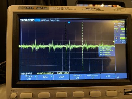
It seems like the Teensy 4 is more prone for ripple than the Teensy 3.2.
I have a 1000uf inserted on the PSU, which takes some of it, but has anyone a suggestion on how to bring it further down?

IMG_0445.jpg
 
When I add this in setup in my example patch, the problems goes away
IOMUXC_SW_PAD_CTL_PAD_GPIO_AD_B1_02=12;

This register controls the drive strength of the pin. Normally drive strength shouldn't matter in a system with good electrical design, especially if using a buffer chip to increase the signal to 5V, with only a short wire between Teensy and the buffer chip.

But the longer the wire between Teensy's pin sending the signal and whatever receives it, the more details like the type of driver chip, the type of wire and physical arragement of the GND return wire, and resistor to match impedance tend to matter.

Especially if you use no buffer chip to boost the signal to 5V level and you try to connect Teensy's pin to a long wire, signal quality can become a difficult problem.


Are somebody able to explain what I have brewed together, and how to proceed further.

I just skimmed over the messages 9 messages on this thread and did not see a description or photos or diagrams of how you've connected Teensy to these LEDs.

The normal way is with this OctoWS2811 adaptor board.

https://www.pjrc.com/store/octo28_adaptor.html

This board has a 74HCT245 buffer chip which increases the signal to 5 volts. It also has 100 ohm resistors which closely match the "characteristic impedance" of CAT5 / CAT6 cable. Those 2 features give you good quality signals over even fairly long cables, like several meters (a couple dozen feet).

The OctoWS2811 page has a "Signal Quality" section which explains the electrical problems in more detail.

https://www.pjrc.com/teensy/td_libs_OctoWS2811.html

Scroll down until you find that section. Look for the oscilloscope waveforms which show real signals with and without impedance match resistors!


But I hope you can understand how this message is mostly guesswork, since I can't see how you've actually connected the LEDs. The best I can say is signal quality problems are a well known issue. Different drive strength settings, which modify how the transitors inside the chip operate, are electrically similar to adding resistance... which is why I'm guessing this may related to your problem. That Signal Quality section of the OctoWS2811 page was written nearly 10 years ago. It really is a well known issue back to the earliest days of OctoWS2811, which was also the time when these single-wire addressable LEDs became widely available, and Teensy 3.0 had just recently been released.
 
Back
Top