IR library I don't need a degree to work out

SteveSFX

Well-known member
Hello all

I have a Teensy 3.2 here, and trying to get the IRremote library working. Used it before, but the latest update is now so madly complicated with 'USE_DEFAULT_FEEDBACK_LED_PIN' and 'ENABLE_LED_FEEDBACK' etc, that I just cannot get it working. No idea why the example called 'Simple Receiver' is anything but :confused:

It fails to initialise the IR at line 59 (I have changed the pin definitions in "PinDefinitionsAndMore.h"). I am using pin 26 as my IR input.

Why it needs to be so complicated I don't know. Can I not get this thing working without the baggage of the "PinDefinitionsAndMore.h" file? I tried to remove it and no-go.

Tried a few other libraries IRlib and IRLib2 and they both had timer issues I believe (both threw up TCNT2 errors?).

Don't want to go backwards to a Pro-Mini, but at least that worked.


Code:
/*
 * SimpleReceiver.cpp
 *
 * Demonstrates receiving NEC IR codes with IRrecv
 *
 *  Copyright (C) 2020-2021  Armin Joachimsmeyer
 *  armin.joachimsmeyer@gmail.com
 *
 *  This file is part of Arduino-IRremote https://github.com/Arduino-IRremote/Arduino-IRremote.
 *
 *  MIT License
 */

/*
 * Specify which protocol(s) should be used for decoding.
 * If no protocol is defined, all protocols are active.
 */
//#define DECODE_DENON        // Includes Sharp
//#define DECODE_JVC
//#define DECODE_KASEIKYO
//#define DECODE_PANASONIC    // the same as DECODE_KASEIKYO
//#define DECODE_LG
#define DECODE_NEC          // Includes Apple and Onkyo
//#define DECODE_SAMSUNG
//#define DECODE_SONY
//#define DECODE_RC5
//#define DECODE_RC6

//#define DECODE_BOSEWAVE
//#define DECODE_LEGO_PF
//#define DECODE_MAGIQUEST
//#define DECODE_WHYNTER

//#define DECODE_DISTANCE     // universal decoder for pulse width or pulse distance protocols
//#define DEBUG // Activate this for lots of lovely debug output from the decoders.
//#define INFO                // To see valuable informations from universal decoder for pulse width or pulse distance protocols
//#define DECODE_HASH         // special decoder for all protocols

#include <Arduino.h>

/*
 * Define macros for input and output pin etc.
 */
#include "PinDefinitionsAndMore.h"

#include <IRremote.hpp>

void setup() {
 
    delay(3000);
  
    Serial.begin(115200);
    // Just to know which program is running on my Arduino
    Serial.println(F("START " __FILE__ " from " __DATE__ "\r\nUsing library version " VERSION_IRREMOTE));

    /*
     * Start the receiver, enable feedback LED and take LED feedback pin from the internal boards definition
     */
    IrReceiver.begin(IR_RECEIVE_PIN, ENABLE_LED_FEEDBACK, USE_DEFAULT_FEEDBACK_LED_PIN);

    Serial.print(F("Ready to receive IR signals of protocols: "));
    printActiveIRProtocols(&Serial);
    Serial.print(F("at pin "));
    Serial.println(IR_RECEIVE_PIN);
}

void loop() {
    /*
     * Check if received data is available and if yes, try to decode it.
     * Decoded result is in the IrReceiver.decodedIRData structure.
     *
     * E.g. command is in IrReceiver.decodedIRData.command
     * address is in command is in IrReceiver.decodedIRData.address
     * and up to 32 bit raw data in IrReceiver.decodedIRData.decodedRawData
     */
    if (IrReceiver.decode()) {

        // Print a short summary of received data
        IrReceiver.printIRResultShort(&Serial);
        if (IrReceiver.decodedIRData.protocol == UNKNOWN) {
            // We have an unknown protocol here, print more info
            IrReceiver.printIRResultRawFormatted(&Serial, true);
        }
        Serial.println();

        /*
         * !!!Important!!! Enable receiving of the next value,
         * since receiving has stopped after the end of the current received data packet.
         */
        IrReceiver.resume(); // Enable receiving of the next value

        /*
         * Finally, check the received data and perform actions according to the received command
         */
        if (IrReceiver.decodedIRData.command == 0x10) {
            // do something
        } else if (IrReceiver.decodedIRData.command == 0x11) {
            // do something else
        }
    }
}

In the definitions code:

Code:
#elif defined(TEENSYDUINO)
#define IR_RECEIVE_PIN      26
#define IR_SEND_PIN         31
#define TONE_PIN            4
#define APPLICATION_PIN     5
#define ALTERNATIVE_IR_FEEDBACK_LED_PIN 6 
#define _IR_TIMING_TEST_PIN  7

Any idea what would stop it initialising and what are all these extra pin definitions for? 'SimpleReceiver!!!!!!" (I know I am a bit thick and all that)
 
IDE = 1.8.8
Teensyduino = Loader = 1.45? Where do I find that out?

I hate upgrading the IDE, it always breaks so many things
 
2 places. In Arduino, click Help > About. In the small Teensy Loader window, also click Help > About. Both show info about which version you have.
 
I ran a quick test here, since it's been a long time since I've tested IRremote. TL;DR = works fine on Teensy 3.2.

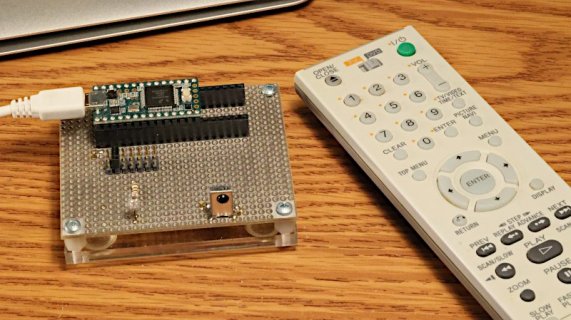
First, I pulled out the board I soldered so many years ago for IRremote testing. It has a IR LED with jumpers to connect to various pins, and a IR receiver module with its output connected to pin 6.

irremote.jpg

I tested with Arduino 1.8.16 and Teensyduino 1.56-beta3 (the latest beta, though 1.55 and other versions should be the same... IRremote hasn't changed lately). Just to be clear, this is the copy of IRremote which Teensyduino installs. I clicked File > Examples > IRremote > IRrecvDump. The only change I made was to edit the pin number, since this board has the hardware on pin 6.

Code:
 * IRremote: IRrecvDump - dump details of IR codes with IRrecv
 * An IR detector/demodulator must be connected to the input RECV_PIN.
 * Version 0.1 July, 2009
 * Copyright 2009 Ken Shirriff
 * http://arcfn.com
 * JVC and Panasonic protocol added by Kristian Lauszus (Thanks to zenwheel and other people at the original blog post)
 * LG added by Darryl Smith (based on the JVC protocol)
 */

#include <IRremote.h>

/* 
*  Default is Arduino pin D11. 
*  You can change this to another available Arduino Pin.
*  Your IR receiver should be connected to the pin defined here
*/[B]
int RECV_PIN = 6;[/B]

IRrecv irrecv(RECV_PIN);

decode_results results;

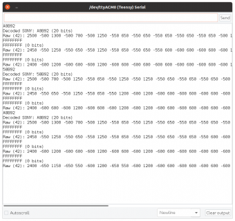
Then I uploaded it to Teensy 3.2 and opened the serial monitor. When I press buttons on that remote control, this is what I see on my screen.

screenshot.png

IRremote really does "just work" on Teensy 3.2 if you use the latest software (or probably any version from the last several years) and just run the examples from the IRremote library Teensyduino installed.

If you have a bunch of stuff you've installed, pay close attention to messages Arduino prints about duplicate libraries. The known good copies from Teensyduino are in {Arduino}/hardware/teensy/avr/libraries. If you install the same library in {Documents}/Arduino/libraries, it will override the known-good copy from Teensyduino. Those duplicate library messages are meant to help you see which version you're really using. Maybe use File > Preferences to turn on verbose output during compilation to make sure you get those messages (otherwise they might only show up when you have a compiler error).

Just use the known good copy Teensyduino installs and this stuff just works.
 
Thanks Paul. I have a huge amount of libraries installed, so I expect its picking the wrong one. I will check.
Thank you for your advice.

With regard to the same prototyping board I am playing with here.... I have 2x Oled screens using the Adafruit_SSD1306.h library, but they have different dimensions - 128x32 and 128x64. They do have different I2C addresses.

Currently, I can only use one or the other.

I declare:
Code:
#define OLED_RESET     -1                                                                                                  // Reset pin # (or -1 if sharing Arduino reset pin)
Adafruit_SSD1306 display(128, 64, &Wire, OLED_RESET);
//Adafruit_SSD1306 display(128, 32, &Wire, OLED_RESET);                                                       // (currently not used)

display.begin(SSD1306_SWITCHCAPVCC, 0x3d);                                                                      // Start the square OLED screen
// display.begin(SSD1306_SWITCHCAPVCC, 0x3c);                                                                   // Start the rectangle OLED screen (currently not used)

All works fine.

Is it possible to control 2x screens at the same time? If yes, how would you address them individually with there respective I2C addresses?

Thanks
 
Nope... never reaches: Serial.print(F("Ready to receive IR signals of protocols: "));

Its exactly as the example. Maybe pin 26 is not suitable?
 
I've never tried to use 2 of those displays at the same time. Looks like they ought to work if using different addresses. Maybe run the Wire library Scanner example, just to double check both are a unique address.

If you're able to access the back side pins, you could connect the other display to Wire1 instead of Wire.
 
IR problem: Nope... never reaches: Serial.print(F("Ready to receive IR signals of protocols: "));

Its exactly as the example. Tried a different pin (not that it should make a difference). Same outcome. Doesn't seem to initialise. No library errors.

Already run the I2C scanner and those two screens are on the 2x I2C addresses in my code. If I comment one or the other out, I can use them.

How do I make 2 sets of the SSD1306 to address them individually within the same program?
 
Before I do any more on this, maybe you could try Arduino 1.8.16 with Teensyduino 1.56-beta3 (the exact versions I used in msg #5) and run the same IRrecvDump example?

https://forum.pjrc.com/threads/68748-Teensyduino-1-56-Beta-3

That particular example does not have the string "Ready to receive IR signals of protocols: ". Would be better if it did, as it just sits there printing nothing at all until it hears IR signals. If the example you're running has that string, it's a very sure sign you're not running the same code I tested.

Please, do the simple thing first and install the same copy I just verified definitely does work.

I believe that IRremote library access the pin using Arduino's pin access macros, so it should work with any digital pin. If there's reason to believe a problem exists with pin 26, I can investigate. But please before I set up the hardware again (already put it away) make sure you're running exactly the same code I just verified does indeed work.
 
OK. Like I said, I hate updating my IDE, it nearly always breaks stuff. I already have shortcuts to 3x different versions of the IDE because I have projects using libraries that have not been updated and won't run on newer IDE's (mainly displays).

As for the second I2C port, that is a good idea, but then after reading up... I need to use 12C_t3 library? That will then presumably break my I2C comms to my DS3121 RTC, 24LC512 memory IC's, MCP23017's etc.

Not sure I am savvy enough to fix all those issues.

I am I should point out, getting each element working individually, and then moving the code over to my main project... so the IR testing is currently just a standalone routine.

That demo you have above Paul.... throws up 'no setup or loop' errors? Is that something 1.8.16 doesn't do?
I think it's time maybe I tried a new IDE?
 
Thanks Paul. Got both the IR library and the dual screens working on the same I2C bus.

IR just needed the IDE updating.

Am I being stupid? I have a LED on my project (Heartbeat), and I use this little routine to flash it. But it's on all the time, because the millis() are running far faster than 1000 per second.
I am running the Teensy at 96Mhz overclock..... is that why? I thought the millis() would be consistent.

Code:
  if ((millis() - (HeartbeatMillis > 2000)) and (millis() - (HeartbeatMillis < 2010))) {
    digitalWrite(Heartbeat, HIGH);
  }


  if (millis() - (HeartbeatMillis > 4000)) {
    digitalWrite(Heartbeat, LOW);
    HeartbeatMillis = millis();
  }
 
millis() works fine on Teensy 3.2, even overclocked at 96 or 120 MHz.

That code is wrong in multiple ways.

I would recommend to instead use elapsedMillis, which allows for much simpler code.

https://www.pjrc.com/teensy/td_timing_elaspedMillis.html

If you want help with fixing that complicated code, follow the Forum Rule (at the top of every page) by posting it in the form of a complete program anyone can copy into Arduino and run on a Teensy board to reproduce the problem. Before you post your message, please actually copy the code back into a empty Arduino window and upload it to your board to make sure the code you're showing really does compile and reproduce the problem! (the code fragment is not only logically wrong, but also has a syntax error which can't possibly compile) Yes, doing this means some extra work on your part, but in the end it saves everyone a lot of time and lets us help you much better.
 
OK, thanks.

My 'demo' code is such a mess, people probably will just tell me to go away and re-write it!
I'll read up on elaspedMillis then.

Why is my code wrong? I have used that method for years. I know the window of 2000 - 2010 millis() might turn the LED on multiple times, but it ensures it doesn't miss the event.

Last question... honest..... In the Iremote.h library, what does the 12 achieve in the transmission command?

irsend.sendSony(0xa90, 12);

Many thanks, Steve
 
Even if you used that code all the years, it never has worked all the years :)

Code:
millis() - (HeartbeatMillis > 2000)

This subtracts a bool ("is HeartbeatMillis > 2000 ?" - return true or false ) from millis().

Also, "and" is &&
 
Am I being stupid? I have a LED on my project (Heartbeat), and I use this little routine to flash it. But it's on all the time, because the millis() are running far faster than 1000 per second.
I am running the Teensy at 96Mhz overclock..... is that why? I thought the millis() would be consistent.

Also, "and" is &&

'and' instead of && is unusual but perfectly OK. But, you have the parentheses wrong. You probably meant to write:
Code:
if ((millis() - HeartbeatMillis > 2000) and (millis() - HeartbeatMillis < 2010))
{
    digitalWrite(Heartbeat, HIGH);
}

if (millis() - HeartbeatMillis > 4000)
{
    digitalWrite(Heartbeat, LOW);
    HeartbeatMillis = millis();
}
which works. Anyway, this is a very unusual way to program a heartbeat. As Paul mentioned, this is much simpler:

Code:
//....
elapsedMillis stopwatch = 0;

void loop()
{
    if (stopwatch > 2000)
    {
        digitalToggle(Heartbeat);
        stopwatch = 0;
    }
}
 
Code:
elapsedMillis stopwatch = 0;

void loop()
{
    if (stopwatch > 2000)
    {
        digitalToggle(Heartbeat);
        stopwatch = 0;
    }
}

This just throws up errors for me.... I assume I need the #include <Utilities.h> library.

I play around with it later.
 
Here is a complete sketch. No #include statements. Built in Arduino IDE for T4.1

Code:
int Heartbeat = LED_BUILTIN; // LED pin

void setup() {
  // initialize the digital pin as an output.
  pinMode(Heartbeat, OUTPUT);
}

elapsedMillis stopwatch = 0;

void loop() {
  if (stopwatch > 1000) {
    digitalToggle(Heartbeat);
    stopwatch = 0;
  }
}
 
Code:
int Heartbeat = LED_BUILTIN; // LED pin

void setup() {
  // initialize the digital pin as an output.
  pinMode(Heartbeat, OUTPUT);
}

elapsedMillis stopwatch = 0;

void loop() {
  if (stopwatch > 1000) {
    digitalToggle(Heartbeat);
    stopwatch = 0;
  }
}

I just get...

Timer_test: In function 'void loop()':
Timer_test:12: error: 'digitalToggle' was not declared in this scope
digitalToggle(Heartbeat);

^

'digitalToggle' was not declared in this scope
 
What is your IDE, version, Teensyduino version, target? I’m using Arduino 1.8.16, latest TD 1.56 Beta3, Teensy 4.1. I think you should have digitalToggle for any Teensy if your IDE is set up correctly.
 
Back
Top