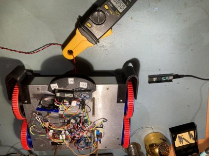
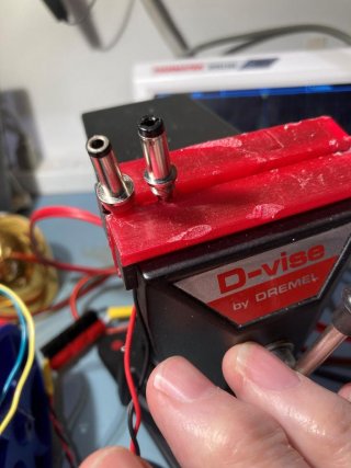
I managed to kill another Teensy 3.5 today when I connected the charging power supply to the robot's charging jack.
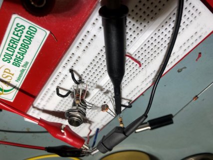
After concluding that I killed the first one by connecting the switched ground line of the power jack directly to a Teensy digital input, I decided to abandon that idea entirely and instead look for +12V (appropriately divided down, of course) on the + side of the charging jack. I installed a 4:1 divider using a 30K and 10K resistor, with a 1uF cap paralleling the 10K, as shown in the attached schematic snippet. Here's the code:
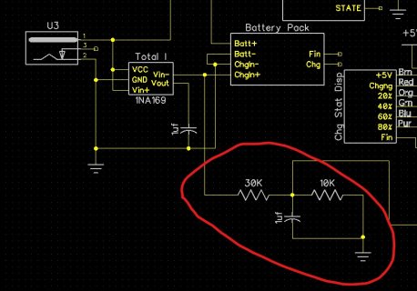
The output from the voltage divider is connected to an analog input (A1 if it makes a difference). I tested this yesterday with my lab power supply set for 12V, and it worked great. However, when I tested it using my 12V MeanWell GST60A12 power supply, the Teensy rebooted a couple of times, and then died completely. No flashing LED (I have the sketch set to toggle the LED every 200mS), no serial output-nada.
Came back today and darned if the Teensy isn't working again! Tested at the A1 input with my lab power supply again - works great (although at 3V, not 12). Moved my lab power supply to the charge jack, and verified that now the analog input reads full-scale at 12V input - no problem. However, if I connect and disconnect the MeanWell supply a few times, I'll get the 'down' USB tone, and the Teensy LED will dim (still flashes, but much dimmer). If I disconnect & connect the USB connector to the Teensy, I'll get the 'up' beat followed almost immediately by the 'down' beat. Looking at the 3.3V output on the Teensy, I can see the voltage go up to 3.3V as it should, but then almost immediately drop back to 1.9V, at which point I get the USB 'down' beat.
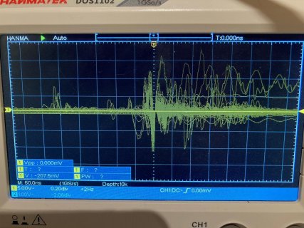
There is obviously something different about the MeanWell PS, but I can't for the life of me figure it out. it scopes out fine on the bench, nice clean 12V DC output. Its a switching supply with the 12V output completely isolated (I checked with an ohmmeter) from the input. I'm officially baffled.
Anyone have any experience with MeanWell sealed switching supplies? I've been using this same PS for years as my battery charging station supply for years with no problems with an Arduino 2560 controller.
TIA,
Frank
After concluding that I killed the first one by connecting the switched ground line of the power jack directly to a Teensy digital input, I decided to abandon that idea entirely and instead look for +12V (appropriately divided down, of course) on the + side of the charging jack. I installed a 4:1 divider using a 30K and 10K resistor, with a 1uF cap paralleling the 10K, as shown in the attached schematic snippet. Here's the code:
Code:
/*
    Name:       Teensy_Pin_Study.ino
    Created:	12/5/2021 5:04:03 PM
    Author:     FRANKNEWXPS15\Frank
*/

#include "elapsedMillis.h"
elapsedMillis mSecSinceLastPass = 0;
const int LED_BLINK_INTERVAL_MSEC = 200;
int pwm_num = 0;
//const int CHG_CONNECT_PIN = 14;
const int CHG_CONNECT_PIN = A1;

#pragma region CHG SUPP PARAMETERS
//02/06/21 added for charge connection debounce
const int CHG_CONNECT_PIN_READING_ARRAY_SIZE = 5;
int aChgConnectReadings[CHG_CONNECT_PIN_READING_ARRAY_SIZE];
const float CHG_CONNECTED_AVG_THRESHOLD = 400;
const float CHG_DISCONNECTED_AVG_THRESHOLD = 100;
float ChgConnectOldAvg;//this is the 'oldTot' in 'IsChargerConnected(bChgConnect, oldTot)'
long chgStartMsec;//added 02/24/17
volatile bool bChgConnect = false; //updated every MSEC_PER_LOOP Msec
#pragma endregion CHG SUPP PARAMETERS

void setup()
{

	Serial.begin(115200);
	delay(1000);

	//pinMode(CHG_CONNECT_PIN, INPUT);
	pinMode(CHG_CONNECT_PIN, INPUT_PULLDOWN);
	pinMode(LED_BUILTIN, OUTPUT);
	mSecSinceLastPass = 0;
}

void loop()
{
	if (mSecSinceLastPass >= LED_BLINK_INTERVAL_MSEC)
	{
		mSecSinceLastPass -= LED_BLINK_INTERVAL_MSEC;
		digitalToggle(LED_BUILTIN);

		//check for charger connection
		bChgConnect = IsChargerConnected(ChgConnectOldAvg);

		Serial.printf("%lu\t%3.2f\t%d\n", millis(), ChgConnectOldAvg, bChgConnect);

	}

}

void CheckForUserInput()
{
	const int bufflen = 80;
	char buff[bufflen];
	memset(buff, 0, bufflen);

	if (Serial.available() > 0)
	{
		// read the incoming byte:
		int incomingByte = Serial.read();

		// say what you got:
		//Serial.print("I received: ");
		//Serial.println(incomingByte, HEX); //chg to HEX 02/18/20

		//02/18/20 experiment with multiple commands
		switch (incomingByte)
		{
		case 0x43: //ASCII 'C'
		case 0x63: //ASCII 'c'
				break;

			//left side wall tracking
		case 0x4C: //ASCII 'L'
		case 0x6C: //ASCII 'l'
			break;
		}
	}
}

bool IsChargerConnected(float& oldAvg)
{
	//Purpose: Determine if robot has connected to charger
	//Inputs:
		//aChgConnectReadings = byte array containing previous readings
		//oldTot = previous readings total
		//curState = current value of bChgConnected
	//Outputs:
	//	true when array total * CHG_CONNECT_PIN_READING_ARRAY_SIZE > CHG_CONNECTED_AVG_THRESHOLD
	//	false otherwise
	//Procedure:
	//	Step1: update prev reading array total
	//	Step2: return TRUE if array total * CHG_CONNECT_PIN_READING_ARRAY_SIZE > CHG_CONNECTED_AVG_THRESHOLD
	//			return FALSE otherwise
	//Notes:

//Step0: change pin from OUTPUT LOW to INPUT_PULLUP and wait 10mS for .01cap to charge
	//pinMode(CHG_CONNECT_PIN, INPUT_PULLUP);
	//delay(10);

	//Step1: update prev reading array total
	int newReading = analogRead(CHG_CONNECT_PIN);
	int oldReading = aChgConnectReadings[0];

	for (size_t i = 0; i < CHG_CONNECT_PIN_READING_ARRAY_SIZE - 1; i++)
	{
		aChgConnectReadings[i] = aChgConnectReadings[i + 1];
		//Serial.printf("%d: %d\n", i, aChgConnectReadings[i]);
	}
	aChgConnectReadings[CHG_CONNECT_PIN_READING_ARRAY_SIZE - 1] = newReading;

	float newAvg = (oldAvg* CHG_CONNECT_PIN_READING_ARRAY_SIZE - oldReading + newReading)/ CHG_CONNECT_PIN_READING_ARRAY_SIZE;
	//Serial.printf("newAvg = %2.3f, oldAvg = %2.3f\n", newAvg, oldAvg);
	oldAvg = newAvg;

	bool retStatus = newAvg > CHG_CONNECTED_AVG_THRESHOLD;

	return retStatus;
}
The output from the voltage divider is connected to an analog input (A1 if it makes a difference). I tested this yesterday with my lab power supply set for 12V, and it worked great. However, when I tested it using my 12V MeanWell GST60A12 power supply, the Teensy rebooted a couple of times, and then died completely. No flashing LED (I have the sketch set to toggle the LED every 200mS), no serial output-nada.
Came back today and darned if the Teensy isn't working again! Tested at the A1 input with my lab power supply again - works great (although at 3V, not 12). Moved my lab power supply to the charge jack, and verified that now the analog input reads full-scale at 12V input - no problem. However, if I connect and disconnect the MeanWell supply a few times, I'll get the 'down' USB tone, and the Teensy LED will dim (still flashes, but much dimmer). If I disconnect & connect the USB connector to the Teensy, I'll get the 'up' beat followed almost immediately by the 'down' beat. Looking at the 3.3V output on the Teensy, I can see the voltage go up to 3.3V as it should, but then almost immediately drop back to 1.9V, at which point I get the USB 'down' beat.
There is obviously something different about the MeanWell PS, but I can't for the life of me figure it out. it scopes out fine on the bench, nice clean 12V DC output. Its a switching supply with the 12V output completely isolated (I checked with an ohmmeter) from the input. I'm officially baffled.
Anyone have any experience with MeanWell sealed switching supplies? I've been using this same PS for years as my battery charging station supply for years with no problems with an Arduino 2560 controller.
TIA,
Frank


