Hello Everyone,
firstly I would have to thank you for your valuable inputs in similar topics that I used during now 1.5 years long project.
I am a hobby enthusiast, not from electrical engineering or programming field. With that being sad, you can conclude that I am a rookie but really into robotics") . I followed some open source tutorials that were incomplete regarding electrical scheme and components but I managed my robot to work. I was really proud.
. I followed some open source tutorials that were incomplete regarding electrical scheme and components but I managed my robot to work. I was really proud.
Now to the problem, battery lasted really short and this is probably a good time to explain components.
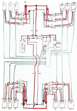
1. 12 DOF robot with 12 x MG996R 10kg/cm .- each set to 6v and potentially max 2.5A in stall
2. 1x Teensy 3.6 @ 5V
3. 1x WiFi Adapter 5v to 3.3v
4. 1x WiFi NRF24L01+ 2.4GHz which is operating on 3.3v
5. 4x 10A DC-DC 6.5-60v to 1.25-30v Adjustable Buck Converter to power Servos. 1 Per Leg set @ 5v output each (because of the small battery pack).
6. 1x MPU-6050 Beschleunigungssensor 3 Achsen Gyroskop set @ 5V
7. Wires are as short as possible - according to recommendation
8. For Signal Wires, I am using CAT5e Networking Cable (SFTP) to minimize interference
9. (Working Battery) Battery in Parallel 2x 7.2V, 1200mAh, NiMH giving a total of 7,2V 2400 mAh and 17.28W
10. Step Down Converted to power Teensy and connected components (Wifi, MPU)
DC-DC Buck Voltage Converter 4.5-40V 12V To 5V/2A.
The above setup worked (for 1.5 years long) but the battery lasted really short - max 10 min and even shorter if movement was complex (yaw, pitch ....) .
So I thought I have a BlackandDecker Li-iOn battery 18V, 2A = 36W
Above components (stepd down converters) had a "declaration" that can sustain such voltage/current so I mounted this battery. As a consequence legs started twitching, jittering ..... but nothing burned (this is good right)
I measured component No 5. DC-DC Converters for Servos - even without servos connected and the output was simply fluctuating - 2v then 5 volts then 3v ..... after that I found on the internet that this component is not quite built correctly therefor the behavior.
I decided to buy - per servo buck converters and I decided for
5. Mini DC-DC Step-down Spannungsregler MP1584EN Buck Power Module Input 4.5V ~ 28V and Output 0,8~ 20V - set to 6V this time as I wanted my servos to move quicker with more powerful battery.
As a result two out of 6 regulators started smelling on burn, were extremely hot, legs were twitched and jittery once again and I disconnected all servos and observed the same behavior of fluctuating voltage on all converters.
At this point I started reading on the internet and on some forums it was written to use UBEC converter, they are built to do a step down for a professional and semi pro RC toys powering servos. I decided to replace my current No 5 solution and to potentially purchase 12 UBECS - one per servo.
5. UBEC Purchased - Hobbywing HW86010010 BEC 3A UBEC Regler for 2-6s LiPo.
with 5.5V-26V (2-6S Lipo or 5-18 cells NiMH /NiCd) and with the ouput 5V/3A oder 6V/3A.
18 cells nimh is around 21V and my current battery is 18V
I purchased only 3 of these to test a single leg but I mounted only one to test failed DC-DC converted.
Jumper was set to 6V output.
Now to the ultimate issue and the main questions:
It took only 1.5 sec there was no burn, smell, nothing, all servos just buzzed for a second and then silence. Ultimately I checked Teensy and it burned (only teensy connected via USB) - no reaction on PC, no lcd, it started to be extremely hot so I unplugged it. Why damn?
Can someone explain me please:
1. Why UBEC caused a Teensy Burn. I assume that servo is now faulty and let voltage through the signal wire back to teensy causing the burn.
2. Any recommendations on which step - down - proven converter shall I use for described battery?
3. Can Li-ion battery itself be a problem?
4. How to prevent future burns of teensy - is there a way to isolate or place a fuse for a signal wire and how to do that (e.g which fuse to purchase)....
Thank you once again for your help and I am really sorry for my long novel but I hope that it explained the situation at least a bit.
I posted the very same question in Arduino forum (link below) but there is a open question where teensy forum is better suitable:
https://forum.arduino.cc/t/stepdown-buck-question/937143
firstly I would have to thank you for your valuable inputs in similar topics that I used during now 1.5 years long project.
I am a hobby enthusiast, not from electrical engineering or programming field. With that being sad, you can conclude that I am a rookie but really into robotics
. I followed some open source tutorials that were incomplete regarding electrical scheme and components but I managed my robot to work. I was really proud. Now to the problem, battery lasted really short and this is probably a good time to explain components.
1. 12 DOF robot with 12 x MG996R 10kg/cm .- each set to 6v and potentially max 2.5A in stall
2. 1x Teensy 3.6 @ 5V
3. 1x WiFi Adapter 5v to 3.3v
4. 1x WiFi NRF24L01+ 2.4GHz which is operating on 3.3v
5. 4x 10A DC-DC 6.5-60v to 1.25-30v Adjustable Buck Converter to power Servos. 1 Per Leg set @ 5v output each (because of the small battery pack).
6. 1x MPU-6050 Beschleunigungssensor 3 Achsen Gyroskop set @ 5V
7. Wires are as short as possible - according to recommendation
8. For Signal Wires, I am using CAT5e Networking Cable (SFTP) to minimize interference
9. (Working Battery) Battery in Parallel 2x 7.2V, 1200mAh, NiMH giving a total of 7,2V 2400 mAh and 17.28W
10. Step Down Converted to power Teensy and connected components (Wifi, MPU)
DC-DC Buck Voltage Converter 4.5-40V 12V To 5V/2A.
The above setup worked (for 1.5 years long) but the battery lasted really short - max 10 min and even shorter if movement was complex (yaw, pitch ....) .
So I thought I have a BlackandDecker Li-iOn battery 18V, 2A = 36W
Above components (stepd down converters) had a "declaration" that can sustain such voltage/current so I mounted this battery. As a consequence legs started twitching, jittering ..... but nothing burned (this is good right)
I measured component No 5. DC-DC Converters for Servos - even without servos connected and the output was simply fluctuating - 2v then 5 volts then 3v ..... after that I found on the internet that this component is not quite built correctly therefor the behavior.
I decided to buy - per servo buck converters and I decided for
5. Mini DC-DC Step-down Spannungsregler MP1584EN Buck Power Module Input 4.5V ~ 28V and Output 0,8~ 20V - set to 6V this time as I wanted my servos to move quicker with more powerful battery.
As a result two out of 6 regulators started smelling on burn, were extremely hot, legs were twitched and jittery once again and I disconnected all servos and observed the same behavior of fluctuating voltage on all converters.
At this point I started reading on the internet and on some forums it was written to use UBEC converter, they are built to do a step down for a professional and semi pro RC toys powering servos. I decided to replace my current No 5 solution and to potentially purchase 12 UBECS - one per servo.
5. UBEC Purchased - Hobbywing HW86010010 BEC 3A UBEC Regler for 2-6s LiPo.
with 5.5V-26V (2-6S Lipo or 5-18 cells NiMH /NiCd) and with the ouput 5V/3A oder 6V/3A.
18 cells nimh is around 21V and my current battery is 18V
I purchased only 3 of these to test a single leg but I mounted only one to test failed DC-DC converted.
Jumper was set to 6V output.
Now to the ultimate issue and the main questions:
It took only 1.5 sec there was no burn, smell, nothing, all servos just buzzed for a second and then silence. Ultimately I checked Teensy and it burned (only teensy connected via USB) - no reaction on PC, no lcd, it started to be extremely hot so I unplugged it. Why damn?
Can someone explain me please:
1. Why UBEC caused a Teensy Burn. I assume that servo is now faulty and let voltage through the signal wire back to teensy causing the burn.
2. Any recommendations on which step - down - proven converter shall I use for described battery?
3. Can Li-ion battery itself be a problem?
4. How to prevent future burns of teensy - is there a way to isolate or place a fuse for a signal wire and how to do that (e.g which fuse to purchase)....
Thank you once again for your help and I am really sorry for my long novel but I hope that it explained the situation at least a bit.
I posted the very same question in Arduino forum (link below) but there is a open question where teensy forum is better suitable:
https://forum.arduino.cc/t/stepdown-buck-question/937143