Teensy 4.0 Brushed Motor and Mosfet get hot

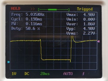
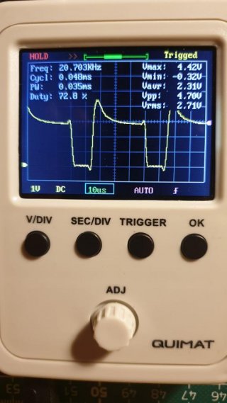
It looks like the MOSFET not only does not open completely but also does not close completely. At the time it is closed, the voltage across it is only 3V, while the voltage on the power supply is 3.8V, which means 0.8V drops on the motor, which means a current flows through the MOSFET (and the motor) even when it should be completely closed.
Probably, no matter how trite it sounds, carefully check the connection of all the elements in the schematic. Because the driver-MOSFET bundle does not work correctly even after you have replaced them with new ones. In addition, you can try to remove the driver at all and connect the MOSFET gate directly to the teensy pin.
 
Thanks for the offer Paul, very nice of you. I think I have a few mosfets lying around here myself. But before I do further tests, I will study the pictures so that I can also see what you guys see. Since I have never owned an oscilloscope for more than a few hours, I am still quite inexperienced in interpreting and understanding the graphs.
In particular, the measurement directly on the motor is still very difficult for me to understand. But that is certainly also due to the fact that the curve probably does not yet look the way it should look.

For this reason I'll just start with the GATE - GND measurement and try to form my thoughts.
At least for me the graphic looks quite understandable. I get the impression that the driver turns on and off relatively cleanly. Please correct me, if I am wrong. I'm really grateful for that, that's how I learn.
Paul already said that the curve looks good, although I don't know what exactly he means by that, maybe he just means the fact that you can see anything at all.
What I noticed was, that even when I go from the low voltage range to the higher 5 volt range, where the driver's actual working range is, I couldn't see any major improvements or drastical changes in all the curves and measurements. I also had the impression with different PWM frequencies there were no dramatic changes here either.* Of course, the curves become more rounded at higher frequencies. However, I expected the impact to be greater. Based on the current state of my yet limited knowledge, I would conclude that the driver actually does his job, even in the low range.

Now to the DRAIN-GND. Thanks to your help, we have already been able to find out, that the FET neither opens nor closes completely. The question now is why? Fom my point of view, I would say that it has nothing to do with the frequency or the voltage level. I could also imagine that the error lies in a completely different place.

Just for info, maybe that could play a role too. My copper plate is 1oz thick and the motor tracks are several millimeters wide. In my tests they never felt warm.
I will try to connect the teensy directly to the mosfet without a driver. Maybe with a new teensy board.

Now over the holidays I have enough time to think about it and I am really grateful for your help :)
 
I'll try to explain the situation from my point of view: when I said that the signal on the gate looks good, I meant that it looks exactly as it should. That is, the driver appears to be working correctly. But, judging by the voltage on the motor, drain, and source - the MOSFET does not work correctly. FET can work incorrectly for only three reasons: 1 - it is not driven correctly, 2 - it burned out, 3 - it is connected incorrectly.
1. Judging by the gate voltage diagram, the MOSFET is controlled correctly, but do not forget that the driver can start working correctly only at the moments when you touch its output with the oscilloscope probe (yes, the probability of this is 1% or even less, but not zero. I saw such situations more than once and this is not a miracle and do not ask me to explain it, just accept as a fact that this sometimes happens).
2. Burning the MOSFET is not that difficult. For example, you can shoot it with static voltage and it will die quietly without any visual effects such as smoke or a cracked package. But you had changed it for a new one which works exactly the same. That can mean, either the new one also burned out or the reason is other.
3. As always, you are confident in the circuit (all people who have experience in electronics for less than 10 years are always sure that the circuit is assembled correctly - this is a tradition :) )
So - all three reasons why the FET can not work are excluded, the question remains why does it still not work? :)

How I would try to find out the problem:
1. unsolder the gate of the FET from the board so that it hangs in the air and check it with a multimeter. In diode test mode, the multimeter should show infinite resistance from the gate to the drain and to the source in any polarity. If it is not so - FET is out of order.
2. If the MOSFET is normal, connect its gate directly to the teensy pin, take a pin that is not connected to the driver and toggle it between 0 and 1 every 5 seconds.
Code:
void setup() {
    pinMode(6, OUTPUT);
    analogWriteFrequency(6, 20000);
    analogWrite(6, 128);
    pinMode(7, OUTPUT);
}
// the loop function runs over and over again until power down or reset
void loop() {
    digitalToggleFast(7);
    delay(5000);
}
Disconnect the motor with the diode and connect a 50-100 ohm resistor instead. (A current of 50-100mA will be sufficient for testing and at the same time will not burn the resistor at the seconds). Check with a multimeter how the circuit works. When the MOSFET is open, there is the full supply voltage should be present across the resistor, the resistance of your open MOSFET is only 40mΩ. When the MOSFET is closed, the voltage across the resistor should be 0. If something is wrong, change the transistor, if it does not help, remove the transistor from the circuit and connect everything with wires to be sure that there is no error in the printed board itself.
3. When everything works, increase the control frequency to 10-20 kHz and check the same voltages with an oscilloscope.
4. When it works, connect the driver between the teensy and the FET gate (although we can create another holy war there about if the driver is needed there :) ) and check it with an oscilloscope if everything works as before.
5. If everything works, change the resistor back to the motor. Do not forget about the shunt diode across the motor, without it the MOSFET can burn out either immediately or sometime in the future. If it suddenly does not work, return the resistor again and check if it still works with the resistor, if it works with the resistor but not with the motor, try repeating steps 2-4 but with the motor.
6. If you have gone through all the steps and as a result, nothing works, you can sit down and start crying ... But I believe that it will not come to that :)
 
I think we have to take into account the electromotive force (EMF) that is generated by the motor when the current through the motor is halted. This EMF voltage will be seen at the drain of the FET.

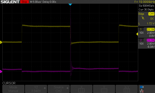
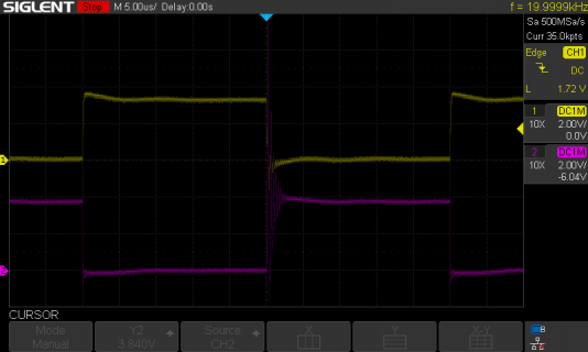
Below are 2 scope screens, one with the motor in place and one with an 8Ω resistor in place. This 8Ω resistance leads to a current of ~210mA on the lab power supply at 3.7V.
Yellow trace is Vgs, purple trace is Vds.

With DC motor:

SDS00056.png

With 8Ω resistor:

SDS00057.png

From the bottom image you can safely conclude that the FET is really closing.
The top image could lead you into thinking the FET does not really close?
To be honest, I'm not sure whether the FET is fully closing with the DC motor in place or that we are looking at the EMF voltage - I have limited knowledge here.

Paul
 
Wow thats awesome thank you both for your many thoughts and efforts! :)* You seem to have a lot of experience.
Kthos I will carry out your steps and hope that in the end I won't cry.
I've only been building my own PCBs for a year, so I don't have that much confidence in my schematics yet and I am always surprised how complicated such a mosfet or motor control can be.
Paul, what you say about the EMF also sounds very interesting. So maybe I should find out how I can better derive the generated voltage from the motor. Maybe a diode is not enough.
The first thing I will do is connect the Teensy without a driver and follow the steps from Kthos.*Hopefully that brings light into the dark. But probably after Christmas.*

Now I'm looking forward to spending time with my family.
Merry Christmas :)
 
Hello and Happy New Year, especially to Khtos and Paul, who helped me a lot.
I have now resumed testing and have new results. This is what I did:

1. First I exchanged the Teensy, this did not lead to any change, the Mosfet got hot immediately. So used old Teensy again(!)
2. Then I soldered the UT4404 in air with no driver - No difference.
3. The same thing again this time with the driver - No difference.
4. I switched to a new mosfet - No difference.
5. I wanted to see how another PWM pin behaves. This is where found out by accident that the Pin22 is not working. (Always 0V) Possibly scrapped by testing. So it was better to take the new Teensy(!)
6. Then I decided to test a different mosfet. The good old BUZZ11 (mosfet). At first without driver. It gets hot, which makes totally sense:
buzz11_without_driver.jpg

7. Buzz11 with driver. Works very good event at lower voltage! Temperature is ok.
buzz11 with driver.jpg

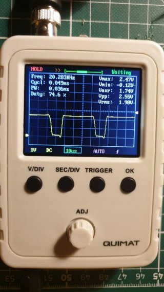
8. UT4404 soldered in the air with driver. It works too????????? What the hell! Then soldered it back to the board with same result! The temperature is also much lower. This is exactly how the curve should look like.
UT4404 with driver.jpg

My guess now is that due to the broken PWM pin, the other Teensy pins might not be able to supply enough current, so that even the gate driver received too little current ... which surprises me, because the motor previously worked without a driver, albeit with very less Power. I'm slowly going crazy here. Well, a new Teensy worked wonders anyway. I probably had a broken mosfet in step 1...
I now take a new PCB, the new Teensy, new motors
and test everything again.
 
I have now taken a new PCB and soldered the missing components (actually only the driver).
3 of the 4 motors run wonderfully. No heat development and lots of power!
The 4th motor, however, only started very briefly, then stopped and did not start again. (Only when I heat the Mosfet does the motor start to conduct again briefly: D)
I remember having this behavior on my first PCB...

Well, I felt like I replaced the mosfet and the driver with new ones a dozen times. Every time the same. The engine only starts up briefly. The drivers are perfectly fine.
However, my measurements showed that the mosfet does not open. Even if I solder the whole thing in the air, no difference!
Then I soldered a Buzz11 to it and it works immediately. What kind of strange mosfets are these? Or am I missing something? Maybe I'm just too stupid!

I am tired of it! I ordered new PCBs, this time with a totally different mosfet.

Perhaps one of you has an idea why the Mosfet does not open and behaves like this.
 
3 of the 4 motors run wonderfully. No heat development and lots of power!
The 4th motor, however, only started very briefly, then stopped and did not start again. (Only when I heat the Mosfet does the motor start to conduct again briefly: D)
Well, that sounds like that one FET is broken. Perhaps killed by static when touching the pins? Who knows... I assume you swapped the motors to rule out the motor and its wiring?

What totally different mosfets are you planning to use now?

Paul
 
Regarding static touch. Maybe my soldering iron tip is under voltage :rolleyes: That would be the only thing I can think of now...
 
Yes exactly, otherwise I cannot use such high frequencies and will have less power.
Do you want to start a holy war, whether the driver is necessary? :D It certainly depends on the application and you could use it without it at low frequencies.

What do you think of the mosfet? I'm still not very experienced on that. But guess it should be ok.
 
I might have decided on a different one, but I just have to use what's in stock. It looks really bad at the moment.
I ordered the last 8 MIC4416 drivers from LSCS for almost 40 euros :eek:
 
No, not going to start a holy war here :)
I just know that the FDD3706 works fine without a driver, see my message #56.
Bought 10pcs here. Still on stock.

Paul
 
Oh yes, that's right, you recommended that to me. I had also looked at it and found it looks very good from the data sheet.
Especially to switch high currents with a low gate voltage. And even quite quickly.
Unfortunately it doesn't fit on my circuit board and is a tad too big. But I will remember the mosfet! thank you
 
The new pcbs arrived yesterday. The motors work with the new AP4410 Mosfets. However, the motors still get very hot.
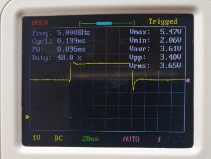
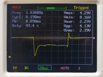
I tried soldering an electrolytic capacitor to the motor, hoping that the drain-source curve would look better. And it did!
I found that with 100uF I have a realtive clean curve and the motor doesn't get as hot anymore. Also about 20% more power!
I would not have thought that...

Without capacitor:
WhatsApp Image 2022-01-15 at 20.36.58.jpg

With 47uF
WhatsApp Image 2022-01-15 at 20.36.58 (1).jpg

Oh, I also tried it with a ceramic, but somehow it didn't really work.
 
Good news! Less hot & more power, nice.
Just checking: so you connected a 47uF (or 100uF) cap from motor+ pin to the source pin of the FET [GND]?
And your 2 photo's above are measured over the FET's drain and source pin?

Paul
 
The capacitor is in parallel with the motor, like the flyback diode. Yes I measured between source and drain of the FET.
But shouldn't it look like this?

I will continue testing tomorrow, it was already late and I still don't understand a lot. I mean, of course it makes total sense somewhere, which is why I wanted to try it, but I don't know anyone who does it that way. A single capacitor to prevent interference, but not such a large electrolytic capacitor.

Furthermore, I've often read that you can just replace elkos with unpolarized ceramics. That's probably not true and I can't imagine it either.

I thought I could, as long as the mosfet switches fast enough, simply increase the frequency so that no capacitor is needed. That's probably not quite the case either.
But I'm still a beginner, at least in this area 😌

Tomorrow it's time to continue testing and learning. Maybe someone will write something clever by then and bring me further 🙂
 
Wasn't a "fast reaction" so important for you? And now you add a large capacitor?
Would have been easier to just decrease the frequency.
 
Nothing changed about that. At the moment I'm only concerned with bringing down the heat from the motors and that's why I am testing. Whether the motors will later regulate quickly enough is another question.
However, I can't say for sure how warm they get with a capacitor. For that I have to test it more extensively. But I can say for sure, that without they get very hot...I tested this a few hours ago with 1khz and 50khz.
Fortunately, the mosfet now stays cool
 
Frank I will also try 250 and 500 Hz. Even if that is rather atypical for a brushed motor. But the capacitor might make it possible. I also wonder how the power consumption behaves...

I want to finish this and finally start programming again 😅
 
Back
Top