Why is digital audio processed in blocks, why not one sample at a time?

Kuba0040

Well-known member
Hello,
This is something I’ve been wondering recently. I am coding from scratch my own software synth on the Teensy 4.0. Why don’t I use the Audio library? – I need something that I can easily add my own modules to and that runs faster. During the development I noticed something.

Observations:
So far, in my implementation each module, (e.g. Filters, mixers), process audio one sample at a time. So, there’s an interrupt at 44.1Khz, and each time it fires all the modules perform all their processing on a single audio sample and then send it to the DAC. But you see, this isn’t how digital synthesis is usually done. The Teensy Audio Library, Mitxela’s MIDI FM synth cable, etc. process data in chunks of for example 200 samples. Why is that? It didn’t seem to make any sense. After all, this approach is way harder to program. I thought that maybe some audio effects are just much easier to accomplish when you can look at more than one past sample, but I couldn’t think of any.

Experiments:
In my tests I’ve noticed that entering and leaving functions takes a lot of CPU time, like 4 cycles. Which makes sense as the CPU must push and pull data to and off the stack. What if audio is processed in large chunks so that we can minimize the time we waste entering and leaving functions by staying in one for a long amount of time. Is that the reason? The only software synth I know that processes it’s audio one sample at a time is the Mozzi library. But it’s written for the AVR architecture where there’s little to no memory so chunks would be expensive and no DMA. I thought that the DMA could have a role in this as well, but it mainly deals in IO, so that’s unlikely.

My question is, is there really a big performance benefit in processing data in chunks, and is the DMA involved in moving the data around, besides just the final output to the DAC?
Thank You for the help.
 
Because it is way more efficient to process the data in blocks.


  • You don't have 44100 interrupts per second - instead 44100 / 128 = 345 only.
  • Any irq, any jump is very very inefficient for te CPU. It's pipeline gets flushed every time and there is even additional heavy overhead. It has to store many value to the stack (and restore it, after that). Some for a sub-routine (that not is inlined) you call for a single sample. Hard to imagine something that is more inefficient than that :)
  • DMA is not needed - the data is NOT copied - it's just a single pointer for each block.
  • The compiler can optimize much better.
 
Thank You. Yea, I haven't even taken into consideration the IRQ losses. Thank you very much.
 
Most algorithms involve some setup overhead. For example, with a filter you need to load the filter coefficients from memory. There can also be quite a bit of unseen overhead the compiler manages automatically, like loading registers with the addresses of variables. With blocks, you suffer that overhead only once per block. The savings add up quickly. For example, on another thread someone recently measured 512 DDS sine wave instances (which use linear interpolation between 2 nearest table entries) consuming 40% of the CPU on Teensy 4.0.

Some of the audio library code makes use of M4 & M7 DSP extension instructions, which allow two 16 bit integers to be stored in the same 32 bit register. Sometimes highly optimized code is designed to process 4 samples per loop by loading two 32 bit registers. This can cut the memory access time in half on M4 which has a 32 bit bus, and even by 1/4 on M7 which has a 64 bit path to memory. But those DSP extension instructions only really help speed up your code if you process at least 2 samples packed into a 32 bit register.

The other huge benefit to fewer interrupts per second is compatibility with other libraries which need interrupts. The audio library uses 2 tiers of interrupt priority, so quick servicing DMA is done at higher priority, then the lengthy DSP work happens at a much lower interrupt priority which allows all other non-audio libraries to have their interrupts work normally. The net result is most other libraries work well while audio is being processed, and the audio work is very robust and resilient to glitching from other interrupts needing some CPU time. When you require an interrupt every 22 microseconds, you can't tolerate other interrupts taking much time to do their work, and if you have to do the DSP work inside that interrupt, odds are high you'll impose interrupt latency onto other non-audio libraries.
 
Any processing involving Fourier transforms will require processing in blocks anyway (such as fast convolution
or spectral analysis).

Its general there is a balancing act between throughput and latency. Most audio lib operations are a few instructions
per sample, but the setup time to call that operation is much larger, so a block size of 1 sample could lead to
one or two orders of magnitude slow down - a very big deal.

Modern I2S ADCs and DACs have latency of many samples anyway (a dozen or so), so aiming for overall single-sample
latency isn't an option anyway, unless you choose non-sigma-delta converters - this is pretty specialized.

Also the human ear is pretty insensitive to delays of a few ms(*), which means a latency of 100 samples or so isn't
usually an issue. The default choice of 128 sample blocks in the Audio library is testament to this.

If you want lower latency one option is simply to go to higher sample rates like 192kSPS, and this has other
advantages (anti-aliasing is easier, rate conversion is easier, lower quantization noise). Professional audio recording
is done at 192kSPS or 384kSPS partly for these reasons.

(*) In 2.9ms, the default block time, sound travels only 1m in air...
 
Hello,
I've done some testing, and encountered some issues, mainly with the DSP Extensions

I am most confused about them. Are you referring to situations like the SMLAWx instruction - better known as “signed_multiply_accumulate_32x16x” from the Audio Library's DSP list - where it has two versions: one performs the multiplication on the bottom half-word, one on the top half-word?

There are many other DSP instructions like this, where they have two versions of each other, one for bottom, one for top. Is this what you are referring to? Because not all DSP instructions work like this. For example, I couldn't find any addition or subtraction instructions that work with half-words like that. (I am looking at this instruction set for the ARM M4 CPU). Even instructions like SUB, which have 16-bit versions, require all operands to be in the bottom halfword. (Link to KEIL ARM site)

Also, these instructions work on M3 CPUs too, which also had me confused as I expected the ARM M4 to have some special DSP features that the M3 CPU is missing in its DSP stuff. <- This is probably just me misunderstanding your post.

So, my question is, how can I perform addition and subtraction on top or bottom half-words, as well as many other operations? Is there something I am missing?
Thank You for the help.

(I intended to reply to PaulStoffregen's post. Not sure why it went to the bottom. I don't have the forum fully figured out yet. Sorry)
 
Last edited:
You'll find a better description in this PDF: https://developer.arm.com/documentation/dui0553/b
For dual signed 16BIT subtraction, for example, the instruction is SSUB16.

There is also a variant SSUB8 which does FOUR 8-Bit substractions.

A nice, short compact comparison of M3 and M4 is here: https://en.wikipedia.org/wiki/ARM_Cortex-M#Cortex-M4.
(More detailed here: https://www.silabs.com/documents/public/white-papers/arm_cortex_m3_and_m4_mcu_architecture.pdf)

BTW, the Teensy 4 uses a Cortex-M7. There is no Teensy with Cortex-M3.
 
There are many other DSP instructions like this, where they have two versions of each other, one for bottom, one for top. Is this what you are referring to?

Yes, more or less.

Here is the ARM v7M reference manual.

https://www.pjrc.com/teensy/DDI0403Ee_arm_v7m_ref_manual.pdf

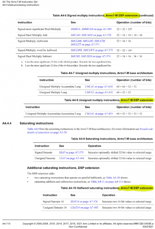
To be precise, the specific instructions are described as "Armv7-M DSP extension" in this manual. For example, on page 110:

screenshot.png


Also, these instructions work on M3 CPUs too, which also had me confused as I expected the ARM M4 to have some special DSP features that the M3 CPU is missing in its DSP stuff.

No, the "Armv7-M DSP extension" instructions do not work on Cortex-M3.


So, my question is, how can I perform addition and subtraction on top or bottom half-words, as well as many other operations?

You can do addition and subtraction, but only in limited ways. See section A4.4.7 on page 112 for details.

And in general, all questions about what you can and can not do with ARM Cortex M3, M4, M7 instructions are precisely (but perhaps tersely) answered by this reference manual.


Is there something I am missing?

From the tone of your question, it sounds like you're assuming these DSP extension instructions are meant to provide a fully featured alternative to the normal Thumb2 instructions (much like how on Cortex-A processors, Thumb2 is a fully featured alternative to the traditional ARM instructions). If so, that would be a mistaken assumption. ARM designed the DSP extension instructions with a pretty narrow focus on specific 16 bit and some 8 bit DSP algorithms. There is only limited support for unsigned integers. Most of the instructions appear to be designed for algorithms which first multiply 16 bit samples by either 16 or 32 bit coefficients, so almost all of the opcode allocated are for signed multiply.

Having used these DSP extension instructions in many places in the audio library, I can say my experience has always been a feeling these instructions provide very limited functionality, but in the places they do, you can get quite a benefit. Sometimes much of the performance benefit isn't mostly from the speed of these instructions, but the way they allow you to use M4 & M7's burst LD & ST feature to move samples faster between registers and memory, and the way certain instructions like the 16x32 multiply allow you to avoid temporarily consuming another register for bits you will just discard, which allows more samples to fit into the limited register set. Every time I have used these instructions, it is a painstaking process of compiling and then looking at the generated assembly and adapt the code to make best use of the 12-13 available registers. It's not (or at least hasn't been for me) anything like normal general programming where you get a feature complete instruction set which can do anything you want. It's only very narrowly focused instructions and reaping their benefit requires a lot of very careful optimization work that is about half way between C and assembly (again, in my personal experience).
 
It can be done sample at a time, but there are more "gotcha"'s. I did it with t3.6 on my eurorack module "dust of time" I had to forgo having any floats in the ISR though. that makes it harder to do something like grab a filter from musicDSP.com and adapt it.

You could use floats, but according to ARM, using floats in an ISR takes about 150 additional cycles to load the registers, I think it may actually be more than that. It is hard to measure because checking the clock counter happens after all that happens and the ISR started. If you only used them in your ISR and nowhere else it might be OK.

there are several "layers" of interrupts.
Higheset priority are gate inputs, they are very small and fast basically just setting a flag to indicate that a gate happened, and action can be taken (depending on the patch)

Then the main audio ISR, it contains:
  • 2 stereo oscillators
  • 4 envelopes
  • 4 LFOs
  • various "FX" processing and mixing
  • SPI out to DAC
  • ADC reads for CV inputs.
  • ways for all those things to get modulated by each other, and other sources.


I can send various commands from the serial monitor to do things like print out how many cycles each section takes for troubleshooting, here is a typical output.

Code:
DAC1+ADC 426
ADSR 324
LFO 370
FUSER 208
Modseq 245
StrDetune 110
OSC 1145
FX 77
TG 355

1 0
2 0

the Teensy 3.6 is overclocked at 240MHz, and it runs at 44100 samples per second. that means there are about 5442(-ISR overhead) cycles available at 100% load. (of course i would not ever want to reach 100%, then the controls will not respond, and FPS would go to 0) I have set up some patches which are "worst case" so i can be almost sure that nothing will overload it.

The next priority is the control loop, it reads values of controls, advances the MUX address, and adjusts various parameters for the audio ISR to use. it runs at 2000Hz.

Then in the main loop(), it gets whatetever time is left to draw the screens, slow counters for the interface, serial in parse, and load and save from SD (audio ISR is stopped for that) It gets about 15-30 FPS with U8G2 + SSD1106 display @ 1MHz i2c, depending on how much the audio ISR is doing.

the downside is I cant use the audio library (but i used a few of the DSP ASM functions), and i dont use floats in the ISR(though that will change in future t4 and up modules)

I like doing it this way because I can get sample accurate response to gates, and everything in the audio ISR can modulate each other with no more than 1 sample delay. it is more "hardware DSP" like than "VST" like, if you get what I mean.
 
Last edited:
Back
Top