Teensy 4.0 + 7" display + PCB

frohr

Well-known member
Hi all,
I have Teensy 4.0 and this display

https://www.buydisplay.com/7-inch-lcd-module-capacitive-touch-screen-panel-i2c-spi-serial
It is 4-wire SPI, 3.3V, 7" capacitive, RA8875.

I have this wiring:
TEENSY/DISPLAY
GND/1
3V3/3
10/5
12/6
11/7
13/8
9/11
GND/31
2/33
18/34
19/35
3V3/37
GND/39
This wiring is tested and works.

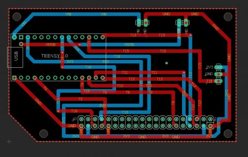
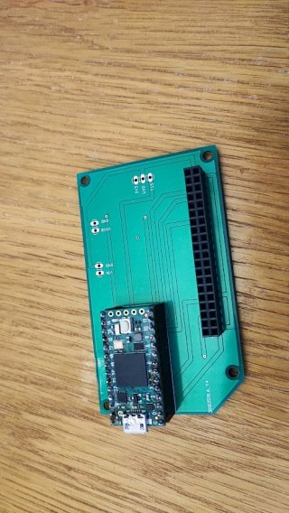
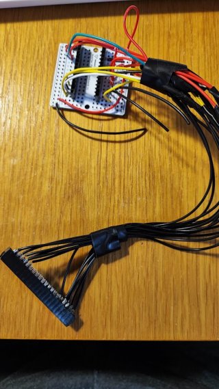
I made PCB, see attached pictures. I use example code from library RA8875 with this:
#define RA8875_CS 10
#define RA8875_RESET 9
#define RA8875_INT 2

Now the problem:

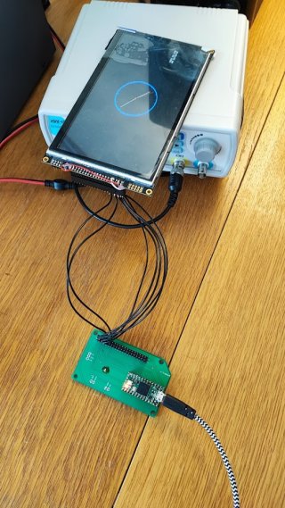
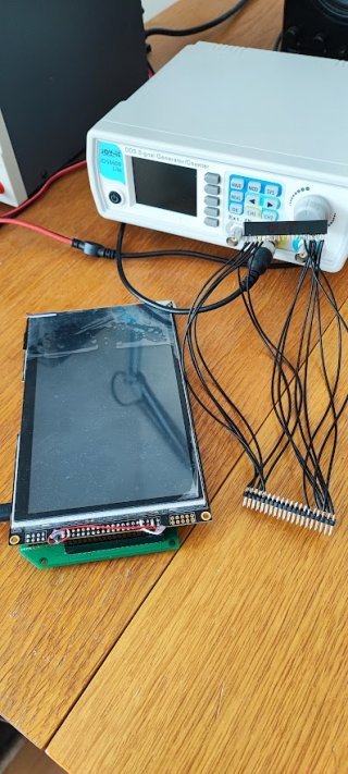
1) If I use "old-wiring" as you can see on picture, it works fine. There is old pinheader form HDD cable.
2) If I use new PCB and soldered wires, it works.
3) If I use pinheader on PCB it does not works.

add 3) I tried to test connection with multimetter and it seems ok from PCB/pinheader to Teensy.
Another test - if I connect display then Teensy serial output will crash. If I disconnect the display, Teensy is restarting and works fine.

Any idea where could be the problem? Teensy works OK, display works OK, direct connection by wires works ok, pinheaders does not work - I tried various typer / producers - this type:
https://www.tme.eu/en/details/zl262-40dg/pin-headers/connfly/ds1023-2-20s21/

Thanks a lot for any advice.


Michal old-wiring.jpgscheme.jpgboard.jpgPCB and Teensy.jpgdisplay-pcb-teensy.jpgdisplay-pcb-teensy.jpg
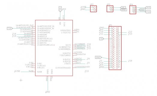
 
Looks like the fills on the pcb are not connected to ground or anything. Perhaps they are picking up noise and messing up the clk T13 to 8. Sometimes a 100 ohm resistor in series with the clock near the Teensy can suppress some noise.
 
There are members up here who use the RA8875/76 displays a lot more than I have.

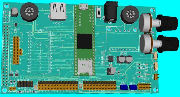
Awhile ago (like a year or two) we were playing around a lot with getting the library to work. While doing that I hacked up a few adapter boards, like a kitchen sink version, which tried to be setup to handle 3 different displays, RA8876, RA8875(4.3") and older 5" which had different connector signals...
RA8875-Round-2.jpg

The one thing I wonder is how you are powering your display. I ordered mine with 5v such that they have their own vr and don't depend on the teensy one, as these do draw a reasonable amount of power
 
There are members up here who use the RA8875/76 displays a lot more than I have.

Awhile ago (like a year or two) we were playing around a lot with getting the library to work. While doing that I hacked up a few adapter boards, like a kitchen sink version, which tried to be setup to handle 3 different displays, RA8876, RA8875(4.3") and older 5" which had different connector signals...
View attachment 27007

The one thing I wonder is how you are powering your display. I ordered mine with 5v such that they have their own vr and don't depend on the teensy one, as these do draw a reasonable amount of power


I am powering the display directly from Teensy 3V3 - I ordered 3.3V display.

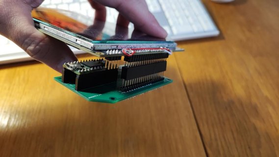
Here you can see, it works if I use wires. If I remove wires and use pinheader, it will crash.
wires-clock.jpg
 
Wonder if processor noise from one is wiping out the other when placed directly over it?

Quick to cover a piece of foil covered both sides in [saran wrap, index cards, paper] some insulator (with a GND strap to foil shield?) and place it between the two when mated?
 
I am powering the display directly from Teensy 3V3 - I ordered 3.3V display.

Here you can see, it works if I use wires. If I remove wires and use pinheader, it will crash.
View attachment 27011

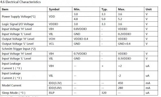
Again not sure how stable that one will work. For example if I look at the specification of the 4.3" display I have...
screenshot.jpg

At 3.3v it might use 450ma..

And the T4 card suggests not using more than 250ma.

The other thing I would check is that in your last picture I think I counted maybe 7 wires connecting the display, but you circuit looks like it has more connections.
So maybe one of those is off, like maybe grounding a power line or the like
 
Again not sure how stable that one will work. For example if I look at the specification of the 4.3" display I have...
View attachment 27013

At 3.3v it might use 450ma..

And the T4 card suggests not using more than 250ma.

The other thing I would check is that in your last picture I think I counted maybe 7 wires connecting the display, but you circuit looks like it has more connections.
So maybe one of those is off, like maybe grounding a power line or the like

You are right, external power will be better, but it works now somehow (of course I do not want damage Teensy).
7 wires is to send data from Teensy to display it. Other 6 are for capacitive touch.
touch.jpg
 
You are right, external power will be better, but it works now somehow (of course I do not want damage Teensy).
7 wires is to send data from Teensy to display it. Other 6 are for capacitive touch.
I sort of assumed that... But you were asking what was different with running with wires versus plugged in... The answer is several more connections between your display and the Teensy, Maybe one or more of those connections are wrong... Like power to gnd or the like.

Note at one point I was using a 3.3v versions of one of the displays and I was finding it flaky...
I thought I might have read something up on the sumotoy wiki: https://github.com/sumotoy/RA8875/wiki
about being power hungry, so I switched to 5v... I modified my 3.3v to be 5v and have a few others...
 
Since it doesn't work when mounted in the connector, I suspect you may have a short between the "unused" pins on the connector. I notice in one picture that the soldered leads are not cut off with wire cutters as is normal so a solution may be as simple as clipping the long leads.
 
TEENSY/DISPLAY

Displaying:
GND/1
3V3/3
10/5
12/6
11/7
13/8
9/11

Touch:
GND/31
2/33
18/34
19/35
3V3/37
GND/39

At first I tried connect only first 7 wires for displaying data and on my last picture are connected all wires included touching. (the same as on PCB). I tried beep it with multimeter and I found no short circuit and all are ok from display to teensy.

I also tried to move teensy on the same place below display as with pinheader and seems there is no noise from cpu.

What I know now:

- No problem with PCB (works OK with wires)
- No problem with display (display is on and touching works)
- Teensy works OK
- Pin-headers works OK with wires

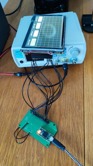
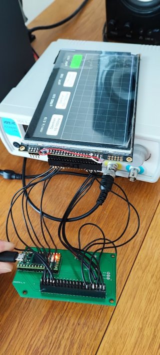
If I remove wires with pin-headers and connect display directly = problem. See pictures.

It is very mystery for me.

works.jpgdoes not work.jpg
 
Again hard to suggest other things from description, but again:

What exactly is the problem when you plug in directly. Hard to know from " Teensy serial output will crash".

Does the program run? Which program? If it runs and crashes, any clues in the output? Are we talking does not start at all, does not complete startup? runs for seconds? minutes? again more specific details.

If it runs try adding more debug output. Maybe add Serial.flush() after many of them to make sure they get out.

When it is plugged in and not powered up, have you measured the resistance values between GND to VCC, 3.3 to 5v, 3.3 to gnd, and see if anything is at or near a short

What stresses are on the connectors, when you are trying this? Is the display touching the T4?

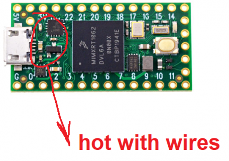
Is the Teensy processor and/or VR overheating as no air circulation. Again you are overusing the VR so it could be real hot? How warm is it when you are using wires?


I will start from the beginning. (code on which I tested it is a bit complicated)
I work now with this easy code:

Code:
#include <SPI.h>
#include <RA8875.h>

#define RA8875_CS 10 
#define RA8875_RESET 9
#define RA8875_INT 2
RA8875 tft = RA8875(RA8875_CS,RA8875_RESET);

void setup() {
  tft.begin(RA8875_800x480);
  tft.setRotation(2);
  tft.setTextColor(RA8875_WHITE);
  tft.setCursor(40, 20);
  tft.println("test");
}

void loop() {
  Serial.println(random(100));
  delay(200);
}


If is display connected via wires, then I can see text "test" on display and random numbers in serial monitor.
If is display connected directly, display is off and I can still see random numbers.
Now I know that program works.

I can see 1,4kOhm between 3V3 and GND, 5V-3V3 - 0 Ohm. I can measure 3.3V on display when connected directly / and the same with wires.

Display is not touching Teensy.

Temperature - wires and display hot, only teensy cold, teensy and display direct cold.

temp.png
 
Sorry again not sure what to tell you. My guess again is the 3.3v vr is not happy.

Not sure about you 0ohm between 5v and 3.3v sounds like shorting out...

If it were me, I would cut the 3.3v line coming from teensy and try jumpering in from some external BEC or VR... I probably have some sitting in boxes,
Maybe something like: https://www.pololu.com/product/2830

Which are nice as self contained just feed it VIN and GND and it can easily use the vin voltages... Some of the others I probably have from Murata require higher input voltages, but they were fine for my usages as it was setup on boards that run servos off of 3s lipo batteries...

But by doing something like that, it can eliminate one possible cause .
 
silly question, but when the display is connected to the headers, are they any pin to pin shorts? Reason I ask is that one of my projects had a RJ45 connector for the display port and during soldering, a small short was created under the connector. Since yours works with wires, this may not be this issue, unless some unrelated wires are shorted.

I like you are stumped in why a wired connection works but not direct. Makes me think of some short caused when the pins have something in them.

Hope this helps
 
Back
Top