Interference with two SPI devices (MS5611 and IMU)

wasserwiesel

Well-known member
Hello everyone,
I have an MS5611 (barometer) and an IMU, which are both connected to the Teensy's SPI0. (Used cs pins: 6 and 8)
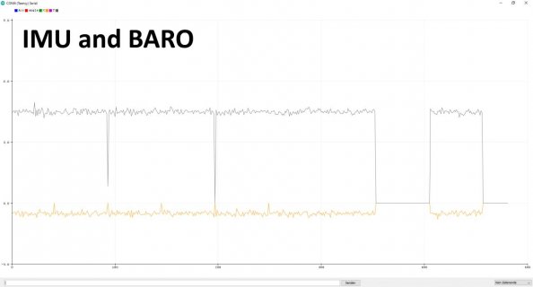
They work properly individually. Together, however, there are many failed measurements at the IMU, regardless of the settings and frequency!
(What you see on both images are the ACC X and Y Angle)
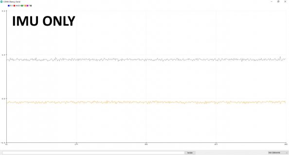
IMU Only.jpg
IMU and Baro.jpg

This is the datasheet of the Baro: https://www.te.com/commerce/Documen...3pdfEnglishENG_DS_MS5611-01BA03_B3-pdfPSC

I had the same problem years ago, but via I2C. Back then I solved the problem by using a different I2C port only for the Baro.
But I don't have any more pins available with my circuit and, to be honest, I refuse, because we're talking about a simple bus protocol here!
I'd rather use a different sensor. Surely it cannot be that a company develops a sensor that blocks the SPI bus?!

The problem probably lies here:
Depending on which sensitivity is selected, the Baro needs a few milliseconds until the values ​​are available.
It is precisely during this time that I get the incorrect measurements. According to the data sheet, this should be possible:
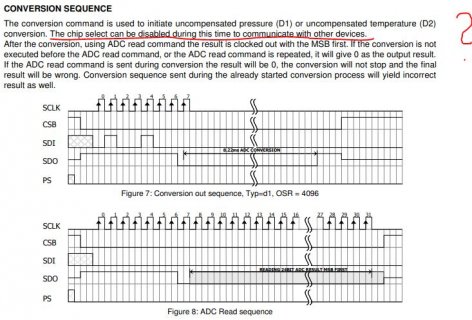
Datasheet.JPG

I cannot do without IMU measurements during this time.
So what do you recommend me to do? Should I just use a BME388/BME390 or am I doing something totally wrong and there is a way to get both to work together?
Here is a code snippet from my baro request:
(I have also seen in other libraries that they add a delay at this point. But that looks like a bad joke to me !?)

Code.jpg

Thanks in advance for your help
 
SPI relies on the CS pins to control which device is active on the bus. You state each device functions individually but they do not play well together. Can you verify that the CS pins are not both active at the same time causing bus interference? Also does each device behave properly on the SPI bus where the data output from each device goes tri-state when CS is inactive.

There is a method to scope the data lines when connected to a resistive voltage divider. @Paul also did an excellent write up on designing SPI bus communications. There are posts in this forum detailing what to do.

Sometimes a 10K pull up resistor on the CS lines is required because the CS pin(s) are floating during the power-on stage when the Teensy pin has not been defined as a driver or input.
 
Hard at times to say, without lots more details. like maybe what IMU, code that demonstrates what you are doing...

Things like: do both devices communicate using the same SPI mode? Sounds like this one does mode 0 or mode 3...

Your code shows a delayMicrosecods(2500);
works, is this the lowest number that works?

Some devices may need a little gap between the end of a transfer and changing the cs pin. did not notice any timing information within the document.

Again all we see in the posting is that you send a byte to some device.

If both devices work ok in the same sketch then it is probably not a MISO issue. That is there are some devices whose MISO may not work in a tristate mode, that is the device might hold that pin either high or low even when they do not have the cs pin asserted.

Sorry I know, not much help.
 
Thank you both for your help! :) Sorry, I know it's not a lot of information, but probably all that's needed. We need to focus on the baro. The IMU works with other devices on the same bus and I've had this problem before.

@grease_lighting: A pull-up resistor is present in all CS lines.
In any case, my code prevents the CS lines from both being low. But of course I can't be 100% sure whether the Teensy will actually do it that way.
Rather, it seems to me that data is going out from the baro on the MISO line, even when the CS line is high. Is there a way to prevent this?

@KurtE: Yes, both of them run in the same SPI mode. I also played around with this, no change.

The 2500us is the time I have to wait according to the data sheet until the data from the Baro is ready. Strange behavior occurs when I make the time smaller. For example at 2100us I have no more values ​​from the IMU at all. Then at 2200us there are a few values ​​again. It seems the Baro just doesn't want to be disturbed or is sending data out without being active. If you look at other projects or libraries, the Baro actually always has its own bus just for itself. But it must be a bad joke...

What you say about tristate mode sounds interesting, but I don't really understand it. Could this be a way I can get this to work?

I also tried to wait a certain time after changing the CS pin, but without success.
 
Just a quick thought:
Many devices that support both I2C and SPI on the same pins cannot be shared as SPI - these chips respond to clocks even when CS is HIGH/inactive,
since CS high means "I2C mode"

I think you can use the MS5611 on I2C alongside the IMU on SPI.
 
Hello MarkT, thank you very much for your answer. Very interesting, first time hearing this. Sounds like a possible explanation. But that sounds somehow like a bug from the device. Maybe there is a way to change these clocks so that the Baro doesn't react to them :confused: How about pull ups for the MISO line? There are people who, in addition to the CS line, also connect all other SPI pins with a pull up. But don't understand why.

Yes, connecting via i2c would work. But I have no more pins free or as soon as I do that, that I2C bus is also blocked and I don't want that. If no one else has an idea, I'll use a different baro for my next PCB.

What I just can't get my head around is the following: There hasn't been a better and popular barometer than the MS5611 in the last 10 years and it's still installed everywhere today. Why is there no outcry and complaints that you can only use it alone in the SPI and in the i2C bus. I just can't imagine that...
That's why I still hope that someone here will tell me that it's possible somehow and that I'm just too stupid to figure it out myself ;)
 
Should I ask the manufacturer directly?
My guess probably your best bet, as there is not anywhere enough information here for any of us to try to reproduce the issue and or know specific things to suggest, so we are left with throwing generic darts and hope one of them helps.

That is no full hardware description, like is the device on some breakout board or soldered directly to your board. PU resistor on cs or depend on software... Is there proper decoupling cap... Note: I am software guy ;)
No software shown to be able to guess if problem there. Yes you did show a few lines showing generic send one byte to some object named spi...

For example how does your code time when to output the request to start the conversion sequence and decide when it should then do the read request.


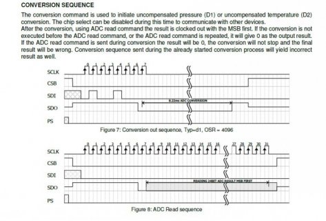
No scope or Logic Analyzer output showing the state of the pins during the conversion. To get a clue on what is actually happening. The spec for the device showing the conversion:
screenshot.jpg

As you mentioned does say that you can release cs to talk to other devices. But again lots unclear in the image. You mention 2.5ms until data is ready, but what is the picture shows a 8.22ms ADC conversion.

It also shows the SDO line low during this... Might it be logically still driving the SDO while it is doing the conversion. As such not allowing the other devices to get get valid input...
See the PJRC web page: https://www.pjrc.com/better-spi-bus-design-in-3-steps/
That talks about tri-state buffer for miso line... If possible you might try to hook up buffer chip and see if that solves your issue.
 
What IMU are you using - I have used a MS5611 with many IMU's without an issue? Are you using a MS5611 library - there are a few available and most have a if result available test so the IMU will not be waiting for the MS5611 to respond?

Here is an example of one that I have used in the past: https://github.com/RobTillaart/MS5611. This one is for I2C

EDIT: Would really help to know more details and see the code you are using.

Only other comment is that I usually use these devices on I2C.
 
Last edited:
Just a quick thought:
Many devices that support both I2C and SPI on the same pins cannot be shared as SPI - these chips respond to clocks even when CS is HIGH/inactive,
since CS high means "I2C mode"
The data sheet for the MS5611 shows separate pins for protocol select and SPI chip select.
 
What IMU are you using - I have used a MS5611 with many IMU's without an issue? Are you using a MS5611 library - there are a few available and most have a if result available test so the IMU will not be waiting for the MS5611 to respond?

Here is an example of one that I have used in the past: https://github.com/RobTillaart/MS5611. This one is for I2C

EDIT: Would really help to know more details and see the code you are using.

Only other comment is that I usually use these devices on I2C.

Are you really sure that you have used the MS5611 with other IMUs on the same bus? If so, that would be good, then the error would probably lie somewhere with me.
 
Back
Top