Teensy4.1 and SPI issues with MAX6952

ksmith

Member
Hello,

I'm trying to interface SPI1 with the MAX6952 and I am having a hell of a time trying to figure out what is going wrong. This is a MAX6952 PDIP with a Teensy4.1. Since the MAX can operate at 3.3V, that is the voltage being used so I can interface directly with the Teensy.

I have the following pin connections:
Teensy -> MAX 6952
1 (MISO1) -> 22 (DOUT)
2 (GPIO PIN 2) -> 23 (CS) * This pin has a 10K pull up.
26 (MISI1) -> 20 (DIN)
27 (SCK1) -> 21 (CLK)

The code I have is the following:
Code:
/* Arduino Libaries */
#include <Arduino.h>
#include <SPI.h>
#include <Audio.h>

/* Local includes */
#include "include/System.h"

/*******************************************************************************
* Module/GLobal Variable Definitions                                           *
*******************************************************************************/
AudioInputAnalog         adc1(A2);           //xy=310,312
AudioMixer4              mixer1;         //xy=455,333
AudioOutputI2S           i2s_1;         //xy=634,404
AudioAnalyzeFFT256       fft256_1;       //xy=636,362
AudioConnection          patchCord1(adc1, 0, mixer1, 1);
AudioConnection          patchCord3(mixer1, fft256_1);
AudioConnection          patchCord4(mixer1, 0, i2s_1, 0);
AudioConnection          patchCord5(mixer1, 0, i2s_1, 1);
int incomingByte = 0; // for incoming serial data 

/*******************************************************************************
* Source Code                                                                  *
*******************************************************************************/
/*******************************************************************************
* Function:     setup
* Description:  Setup function for the LCU application
* Inputs:       None
* Outputs:      None
* Notes: 
*******************************************************************************/
void setup(void)
{
    /* Serial interface */
    while (!Serial && millis() < 5000) 
    {
        /* wait up to 5 seconds for Arduino Serial Monitor */
    }

    //system_StartupSequence(); /* See if this is failing because the i2s is being used. You may need to ignore those pins as well */

    //AudioMemory(30);
    //mixer1.gain(0, 1.0);
    pinMode(2, OUTPUT);
}

void loop(void) 
{
    /*
  if (fft256_1.available()) {
    for (int i=0; i < 20; i++) {  // print the first 20 bins
      //Serial.print(fft256_1.read(i) * 100, 5);
      //Serial.print(" ");
    }
    //Serial.println();
  }
*/
    SPI1.begin();

    while(1)
    {
    
    SPI1.beginTransaction(SPISettings(2000000, MSBFIRST, SPI_MODE0));
    digitalWrite(PIN_02, LOW);
    SPI1.transfer(0x04);
    SPI1.transfer(1);
    digitalWrite(PIN_02, HIGH);
    SPI1.endTransaction();
    
    delay(50);
    
    SPI1.beginTransaction(SPISettings(2000000, MSBFIRST, SPI_MODE0));
    digitalWrite(PIN_02, LOW);
    SPI1.transfer(0x00);
    SPI1.transfer(0x5B);
    digitalWrite(PIN_02, HIGH);
    SPI1.endTransaction();
    
    }
}

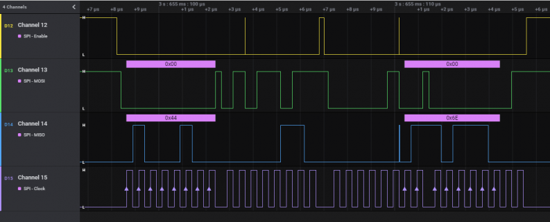
The problem I am seeing for the above code, I am seeing this output:
Capture.PNG

I'm not concerned yet about the input line, but the output never is the data I am trying to transfer. I'm also not sure why the CS line is going high except between the two transactions (and the delay isn't 50ms either). Any thoughts to what I can look at or try? I'm running out of thoughts.

Thanks,
-Kevin
 
Does anyone have any suggestions on what I am seeing? Bit-banging the same code cleared up the signal issues and the data out was sent properly, but it is not displaying anything. I at least want to make sure I can rule out the Teensy and code before I start debugging the MAX.

Thanks,
-Kevin
 
Does anyone have any suggestions on what I am seeing? Bit-banging the same code cleared up the signal issues and the data out was sent properly, but it is not displaying anything. I at least want to make sure I can rule out the Teensy and code before I start debugging the MAX.

Thanks,
-Kevin

Could be a GND problem with the probes.
 
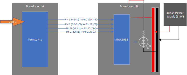
So I did a bit more digging. I found some voltage leaking between the Teensy and the MAX chip and my ground plane was getting noise up to about 0.4V according to my scope. But what I cannot figure out is the "why." Attached is a sketch of the current setup.

Layout.png

When I am testing, the MAX circuit is powered by the power supply and I connect the USB-C cable to the teensy for programming and powering that device. They were on the same breadboard (but no connection to the power rails of the power supply) when I saw this voltage occurring. When I turned the power supply off, the LED on my board (just to indicate power is on) stayed dimly lit. Which of course is how I found the power noise. I then moved the Teensy to a completely separate breadboard and the only things connecting them are the four SPI lines. Again, removing the power from the power supply with the Teensy plugged in, the LED was dimly lit. Removing the USB the LED goes dark.

I repeated the process and removed one SPI line at a time. Removing any single line doesn't change the effect, but after the second or third pin is removed the LED will go out. I cannot think of any direct reason why this is occurring so I am wondering if anyone has any ideas to try?


Also side topic, I eventually want to power the teensy from the 5V pin but also connect the USB cable every now and then for the serial interface, reprogramming, etc. I know from the bottom side I would need to remove the connection between the 5V pad and the PUSB pad. Does the same diode trick defined here work? Could I just solder a surface mount diode between those pins? It is a tight fit to get a through-hole part in there without burning up the pin header...at least for my soldering skills.
 
The LED effect you are seeing is because the active inputs to the unpowered chip are leaking current through the chips input protection diodes and thus putting a little voltage/current on the power rail and through the LED. Since each pin contributes to this current, removing them one at a time lowers the current enough that the LED no longer lights. That is why it is generally not recommended to drive inputs on an unpowered IC.

When you split your breadboard into two, did you connect a common ground between them? If so, it is not shown on the drawing.
 
That is why it is generally not recommended to drive inputs on an unpowered IC.

Its worse than that, its possible to burn out a chip this way as the protection diodes aren't rated for much current.
Always avoid this situation. Its called phantom powering.

The rules with all CMOS logic chips are:

A) Never exceed Vdd+0.3V on any pin, input or output, whether powered or not.

B) Ditto never take any pin lower than -0.3V relative to ground.

If this happens and large currents flow through the protection diodes they may fry, or worse the whole chip can go into
"CMOS latchup" and cook itself (can only be stopped by removing all power to the board). Adding some series
resistance to signals going off the board can protect against this by limiting any currents to a few mA.

Modern CMOS tends to be more robust to latch-up than older designs (now fault currents in the 100's of mA may be
eeded to trigger latchup, which is unlikely in most situations), but its inherent in the CMOS topology so can happen
to any CMOS device if abused hard enough.

One common way to add extra protection to CMOS signals going off-board is backing up the protection diodes with
Schottky diodes external to the chip, diverting any fault currents from entering the chip. It your situation having these
would protect the MAX6952 from the way you've inadvertently abused it - hopefully its not damaged anything, but
avoid phantom powering in the future unless you've got some kind of protection.

C) Never be surprized if an unconnected input reads random values. They do that, its called floating.
 
Back
Top