Hello Teensy-enthousiasts,
I'm trying to embed a teensy 4.0 + audio board into my eurorack setup which involves converting the voltages into ones that the teensy can handle. I've got that all done but for some reason my teensy does not work anymore in this setup. It did partially work before, but no more.
I'm feeding audio to both left & right LINE IN inputs and I get no sound back. Here is a simple 'pass through' that does not work in my setup:
However, if I connect to USB and send audio straight from my PC into line-in and connect my speakers to the teensy, I do get sound. Also my more complex code with audio-effects applied works in that scenario.
I changed my sketch to make the LED on the teensy blink to ensure the teensy is actually running. This worked and I confirmed it is actually running but not processing audio.
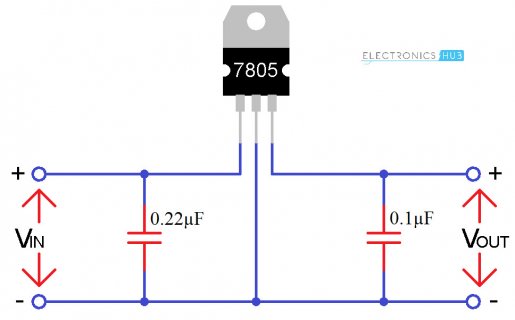
The main difference between the two setups is the way my teensy is powered. In the eurorack setup, I'm converting 12V into 5V using an L7805 with two small caps on both sides, like so:

I used slightly different cap values though. Some of this power is sent to my opamps as well.
The voltage that the teensy sees often hangs around 4.7V and sometimes dips lower (e.g 4.2V). I'm not sure how bad this is since the teensy has its own 3.3V regulator so this should be plenty. It seems to draw around 100mA but it doesn't work during these current measurements (not 100% sure why). I'm rather surprised that the voltage is not stable at 5V at this current It might have something to do with my crappy breadboard or the fact that I don't use a heatsink !?!?
While my audio does not work, the LED blinks. Can it be that the teensy works but somehow, my audio board does not?
I'm quite frustrated because I'm really stuck and messed around quite a bit to find an angle to make it work again. Do you have any suggestions how I can debug this further?
I'm trying to embed a teensy 4.0 + audio board into my eurorack setup which involves converting the voltages into ones that the teensy can handle. I've got that all done but for some reason my teensy does not work anymore in this setup. It did partially work before, but no more.
I'm feeding audio to both left & right LINE IN inputs and I get no sound back. Here is a simple 'pass through' that does not work in my setup:
Code:
#include <Audio.h>
#include <Wire.h>
#include <SPI.h>
#include <SD.h>
#include <SerialFlash.h>

AudioInputI2S            i2s1;
AudioOutputI2S           i2s2;

AudioConnection          patchCord2(i2s1, 0, i2s2, 0);
AudioConnection          patchCord3(i2s1, 1, i2s2, 1);

AudioControlSGTL5000     sgtl5000_1;


void setup() {
  AudioMemory(10);

  sgtl5000_1.enable();
  sgtl5000_1.volume(0.8);
}

void loop() {
}
However, if I connect to USB and send audio straight from my PC into line-in and connect my speakers to the teensy, I do get sound. Also my more complex code with audio-effects applied works in that scenario.
I changed my sketch to make the LED on the teensy blink to ensure the teensy is actually running. This worked and I confirmed it is actually running but not processing audio.
The main difference between the two setups is the way my teensy is powered. In the eurorack setup, I'm converting 12V into 5V using an L7805 with two small caps on both sides, like so:

I used slightly different cap values though. Some of this power is sent to my opamps as well.
The voltage that the teensy sees often hangs around 4.7V and sometimes dips lower (e.g 4.2V). I'm not sure how bad this is since the teensy has its own 3.3V regulator so this should be plenty. It seems to draw around 100mA but it doesn't work during these current measurements (not 100% sure why). I'm rather surprised that the voltage is not stable at 5V at this current
While my audio does not work, the LED blinks. Can it be that the teensy works but somehow, my audio board does not?
I'm quite frustrated because I'm really stuck and messed around quite a bit to find an angle to make it work again. Do you have any suggestions how I can debug this further?

