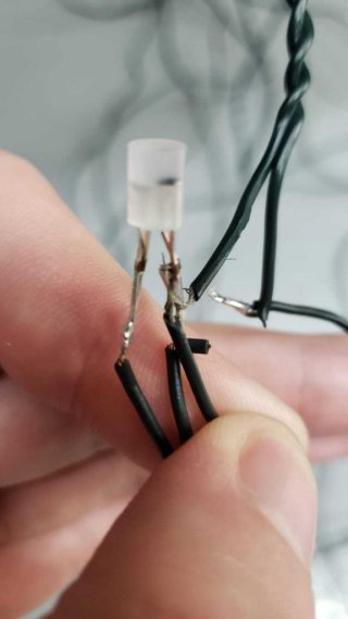
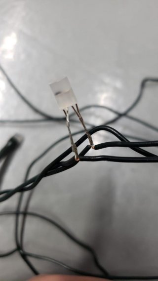
I have some twinkly leds https://www.twinkly.com/ and they are amazing. They are very good for decorations compared to the 12mm ws2811, as they are much smaller. However, the only way to control them is through the mobile app via Wi-Fi.
I know there are some options like x-led to control twinkly pixels from the computer, but it still depends on Wi-Fi communication which, in my opinion, is not so reliable. I would like to control them directly with teensy 3.2 or 4.0, without the need for the Wi-Fi interface that comes from the factory. In this way, it would be possible to connect several LEDs together, customize and still maintain the connection stable through an ethernet module, for example.
For that, I did some tests and measurements, but I still haven't reached a definitive conclusion on how the communication protocol for the pixels works.
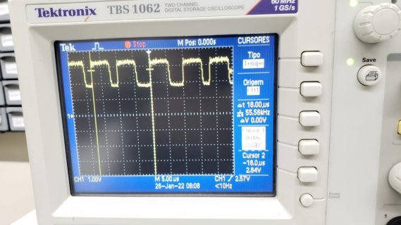
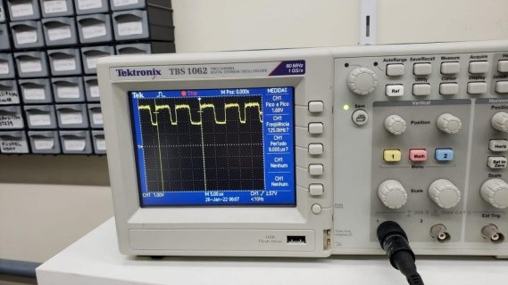
The picture shows a measurement on a single led in a strand of 200 (I have the 400 leds kit, that is divided in 2 strings of 200). The control signal is modulated with the power line.
It appears that the waveform is stable for 6 microseconds and drops to half voltage for 2 or 4 microseconds depending on whether it is a HIGH or LOW bit. When I turned off all the lights, I only visualized the wave with 6us at full voltage and 2us at half voltage, so this makes me think that the 2us corresponds to a bit 0.
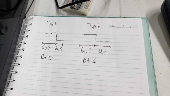
This protocol is quite different from WS2811 and seems to be much slower (at 100 or 125KHz).
Has anyone come to analyze this protocol and perhaps create a library for control ?
Additional Information:
- It seems that each pixel has a unique address, since the data wire (that is the same as power) is connected in parallel with the pixels and has no data in/out logic, unlike in WS2811 where the first pixel takes the first 24 bits and passes the rest.
- Although the power supply is 24V, the pixels are wired in a parallel/series connection so that only approximately 3.35V arrives at each.
-If you remove the pixel cover and look at how the wires are soldered, the led has 4 leads, but the 2 on the left are soldered together and the 2 on the right as well. It seems that it would be a way to define the individual addressing of each one during the manufacturing process using these other terminals perhaps? I will post a picture of the leds later.
I know there are some options like x-led to control twinkly pixels from the computer, but it still depends on Wi-Fi communication which, in my opinion, is not so reliable. I would like to control them directly with teensy 3.2 or 4.0, without the need for the Wi-Fi interface that comes from the factory. In this way, it would be possible to connect several LEDs together, customize and still maintain the connection stable through an ethernet module, for example.
For that, I did some tests and measurements, but I still haven't reached a definitive conclusion on how the communication protocol for the pixels works.


The picture shows a measurement on a single led in a strand of 200 (I have the 400 leds kit, that is divided in 2 strings of 200). The control signal is modulated with the power line.
It appears that the waveform is stable for 6 microseconds and drops to half voltage for 2 or 4 microseconds depending on whether it is a HIGH or LOW bit. When I turned off all the lights, I only visualized the wave with 6us at full voltage and 2us at half voltage, so this makes me think that the 2us corresponds to a bit 0.

This protocol is quite different from WS2811 and seems to be much slower (at 100 or 125KHz).
Has anyone come to analyze this protocol and perhaps create a library for control ?
Additional Information:
- It seems that each pixel has a unique address, since the data wire (that is the same as power) is connected in parallel with the pixels and has no data in/out logic, unlike in WS2811 where the first pixel takes the first 24 bits and passes the rest.
- Although the power supply is 24V, the pixels are wired in a parallel/series connection so that only approximately 3.35V arrives at each.
-If you remove the pixel cover and look at how the wires are soldered, the led has 4 leads, but the 2 on the left are soldered together and the 2 on the right as well. It seems that it would be a way to define the individual addressing of each one during the manufacturing process using these other terminals perhaps? I will post a picture of the leds later.


