Audio shield soldering

dimitre

Well-known member
How do you usually solder Audio Shield on Teensy?
Shield on top? shield under? long pins or short pins? if short, what do you use as a spacer?

I've soldered mine with this double plastic headers (not sure of how it is called) with the audio on top (right in the picture)

But now I'm planning a 3d print enclosure, so wondering of how it can be mounted differently, maybe more compact.
I'm thinking of mounting the next one with the audio shield under (there are some nice holes for fixing) and some long pins without the spacer, so I can define the distance between both. The long pins I have here have this female header, so I can connect the pots and buttons on the top.

Ideas are welcome.
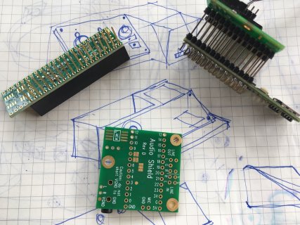
IMG_0731.JPG
 
You could also mount them side by side, I have myself not been thinking of that variant as I thought the wires got to long that way.

But have now long pins stackable headers on both the teensy and the audio shield, that way I can decide if I want to have the teensy on top or vice versa.

Maybe I will just go for the side by side variant in the end
 
@manicksan thanks. I thought it was prohibitive to mount side by side with wires, because of some issues I don't remember exactly.
Impedance maybe? Maybe this issue is protoboard only.
Other than that it is easier for me to just solder pins too (lazyness)
 
Great question, Dimitre.
I've been working with pairs of these audio shields, configured as quad outputs. You can mount them above or below the T3.x, depending upon the rest of your connection requirements. Unfortunately, after 1/2 dozen attempts to upload an image, the upload continues to fail, for some unknown reason.
Anyway, over the course of my project's successes and failures, my 1st lesson was to not solder the audio shields directly to the T3.6. They are a major pain to de-solder if/when one of the two boards fail. I ended up using a Dremel to grind down a groove along the pins, until I could snap the audio shield off. Then each pin could be removed with a soldering iron and solder sucker.
Now, use double ended headers like these:
https://www.amazon.com/gp/product/B00U8OCENY/ref=ppx_yo_dt_b_asin_title_o00_s00?ie=UTF8&psc=1
for the T3.6, plus female stacking headers like these:
https://www.amazon.com/gp/product/B07CYYHSSH/ref=ppx_yo_dt_b_asin_title_o01_s00?ie=UTF8&psc=1
for the stacked audio shields on top. The bottom pins on the T3.6 mate with normal female headers that are permanently soldered to the breadboard or PCB.
This way, no matter which board that I kill during development/testing it can be easily replaced. The only down side is that the stacked headers increase the overall height of the module.
Hope these tips are helpful.
Good luck with your project.
:cool:
 
I'm using female pin headers on top of the audio shield, and male pin header under the teensy board. So I don't need to solder them together. The only problem of this setup is that it's not breadboard friendly. But for permanent use, I think it's reliable and stable.
 
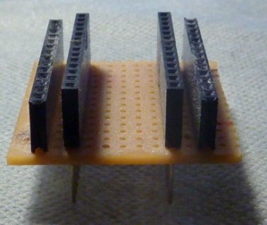
I made a little breakout from headers and stripboard for sandwiching between Teensy and audio shield:
teensy_adapter_top.jpg
Useful for breaking out signals for a screen or whatever.

You could also just use stacking headers on the Teensy in the first place, but I had't done that.
 
Back
Top