MIDI Serial Input Circuit not working on PCB

mikemontauk

Active member
Hello, I have successfully assembled the MIDI input circuit to the Teensy on a breadboard. I implemented the same circuit on a PCB and it is not working. So I went back and built it again on a breadboard successfully, just to be sure I understand it, but I still can't figure out why the PCB embodiment is not working. Would anyone be willing to glance at the attached schematic and board and provide feedback? One notable difference between the breadboard and pcb circuit is on the pcb I used an onsemi-Fairchild S1B rectifier with 1.1 V forward voltage. It was cheap and I had the footprint already and I thought it would do the same job.
A couple knowns - when I tap the Teensy LC RX pin to ground with a loose wire I can typically get some MIDI messages and notes to register in the serial prompt. I assume this is because the connection 'bounce' to ground can look like a midi message.
RX is holding 3.3v and the MIDI connector appears to have 5V to gnd on both pins 4 and 5 during standby. I think I may have fried the opto somehow because everything else seems ok. I'm investing in a scope soon!
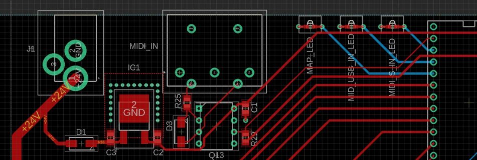
midiinerror.jpg
View attachment midiinerror.pdf
 
Can you post a image of your soldered board as well, both sides.
There should not be 5v on the DIN connector if it's unconnected
 
Hi, sorry for the delay. I purchased an oscilloscope and USB microscope and I have further details, but still have not solved the issue. I also fried 3 Teensy LCs poking probes and wires around with reckless abondon (I'm a Mech-E).

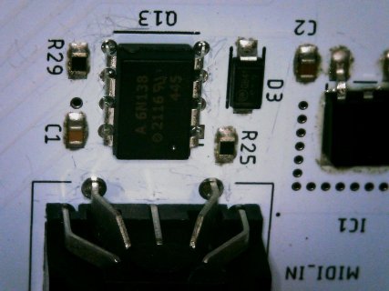
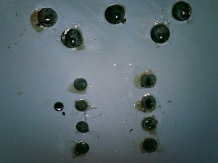
Attached are photos of the board. I know the hot plate solder joints look poor but I checked connections with my multimeter and found all the resistors had the right values and the caps were not shorted. You'll also notice the silk screen pretty scratched up from me probing around and I very well may have shorted any of the board's contacts on multiple occasions.

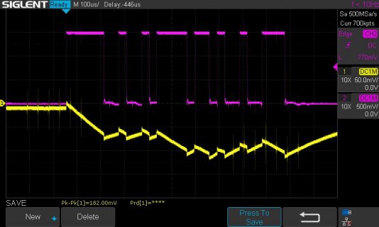
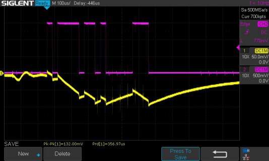
On the scope, the purple trace is anode to cathode on the optocoupler (pins 2&3 of the 6N138). I confirmed Pin 8 is getting 5V. The ouput pin (6) with respect to ground is shown by the yellow trace. I'm not sure what to make of that. It's definitely correlated to the logic levels of the purple trace but its lagging and the rise and fall times very slugish. WIN_20220213_165513.jpgWIN_20220213_165449.jpgSDS00001.jpgSDS00002.jpg
 
Looks like a capacitor is slugging the opto input or output?

Can you confirm the actual component values - R29 the output pullup should be quite low in value, 1k at most.
Can you confirm the 6N138 was bought from a trusted supplier?
 
The purpose of the Opto is to galvanically isolate the sending device from the receiving device so you need to think carefully of how two oscilloscope probes are connected to both devices at the same time. A useful excercise might be to look at the full circuit of the Midi out device connected to the receiving device, then think of what happens when you connect two Scope probes which are NOT isolated from each other. In this case, the 'Scope grounds are gonna make some electrical bridge between two circuits which are supposed to be isolated.

The Scope can display garbage and worse, you can fry stuff. This scenario is where the possible Capacitor @MarkT refers to above is hiding. Is also why the spikes riding on the yellow trace are being picked up.

Double check R25 and R29 values, I've struck mis-labelled resistors, diodes with the Cathode marking on the wrong end as well as dodgy Optos. Such is the nature of "consumer grade" and Murphy's law.

Can we see a single trace with ONE probe connected with Ground to Teensy ground and probe to Opto Pin 6? The Yellow trace is showing output here so let's get a better look at it.

I have reservations about the choice of diode. We usually see a 1N914 here which is a "Fast switching" item, not a rectifier.

I've breadboaded the Opto circuit without the diode and it worked as expected, no surprise as the diode is offering reverse spike protection for the opto's led so am suggesting disconnecting it then see what the 'Scope says.
 
Back
Top