Teensy 4.1 VIN, VUSB, USB host +5V?

liudr

Well-known member
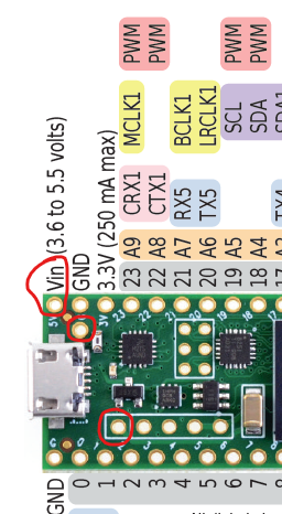
I tested VIN pin (says VIN on reference card but 5V silk screen on board) and the VUSB pin (on back side of card) that is next to it, off from the main row of pins. They are connected. I imagine if I cut the trace between the two pads on the back side, I get them separated. So VIN goes to 3V3 regulator and VUSB is connected to the microUSB connector, correct?

Then what about the +5V pin on the USB host header? It's not connected to VIN or VUSB. So is it connected to the transistor and can be switched on/off? I'm trying to supply power via this 5-pin USB host header but its voltage isn't high enough for bar code scanners only about 4.8xV. I had to rig 5V and GND from another USB connector on my PC. I'm still curious whether it's controlled by a transistor and how to toggle its power. Thanks.
Screenshot 2022-01-31 215639.png

Another question, except for the 3V3 regulator and the +5V on USB host header, nothing really needs 5V, right? So if I supply regulated 3V3 to 3V3 headers, the board should work, right? My regulator has 500mA capability. I wonder if the 3V3 (250mA max) means the onboard regulator can only do 250mA or the regulator has 250mA to spare, i.e. consumption from the regulator is 250mA less than its rated current. Thanks.

One last thing, what is the on/off pin's function?
 
Vin can be separated from VUSB cutting the trace as indicated on the back of the card.

USBHost 5V is supplied from VIN - either USB if trace not cut and plugged into USB, or from the VIN pin supplied power.

The USBHost power is switched on by code when USBHost is activated.

VIN at 5V should make it to the USBHost 5V pin, less the Teensy power used - only with the current capability supplied through VIN. When coming from Device USB the limited ~500 mA supplied current often cannot power the Teensy and active higher current devices. Best solution is to plug a powered USB Hub into the USBHost connector for devices needing more than the available power from VIN that also supplies the Teensy with power. Then in the USBHost code a USBHub element is used to attach the connected devices.
 
pjrc.com has schematics for all boards that might make some things like this easier to understand.

Suppling 3V3 directly to the teensy doesn't sound like a great idea to me. You'll have to look at the schematic and decide for yourself a) that nothing really needs 5V internally and b) that the internal 3v3 regulator isn't going to do anything weird. Don't assume that the regulator, when unpowered sits disconnected. It might have effectively an output short, or there might be a path back through the regulator and you'll end up half powering something you don't want to.

On/off, I have always presumed, turns the board on or off. You can look at the documentation a bit more, but if you don't need it you can probably ignore it. I'd assume for a teensy board (but other times I'd check), that it's pulled so that if you don't drive it the T's enabled.
 
Thanks Edward and defragster. I didn't know schematics are published. I must have been entirely on the store page and only saw pinouts.

Here is the schematics:

https://www.pjrc.com/teensy/schematic.html

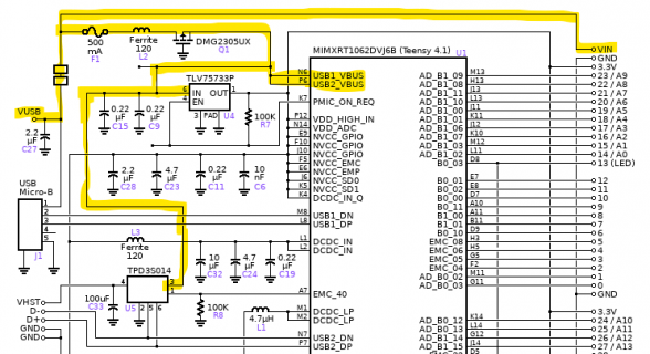
So according to the schematics, VUSB is from the microUSB connector. If I cut the jumper's trace, Then I separate VUSB from VIN, which I think is the single pin hole on the screenshot I posted. This goes through a fuse, a ferrite bead, a transistor (prevent back-filling USB host?), then to USB1_VUSB and USB2_VUSB. These pins might be used to detect bus insertion or something, for both USB ports? Then there are two more places, a 3.3V regulator TLV75733P. This regulator is rated 1A so I guess the 3.3V 250mA max means the processor + FLASH consumes up to 750mA. Its EN is connected to a PMIC_ON_REQ pin on the processor (not sure what the pin does). Then the 5V goes to TPD3S014, which is a protection circuit against over current and TVS for USB data pins. I think my best chances is to short VIN with VUSB so the thin jumper trace won't bother me. The processor needs quite some power so may have to have it connected to a USB host although I wanted to use external power and claim say 10mA on USB device config.

The ON/OFF is connected to an ONOFF pin on the processor. I'll have to read the spec sheet to figure this out. It's got no pullup or down so probably internal pullup like some EN or (RESET) pins.
Screenshot 2022-02-01 090939.png
 
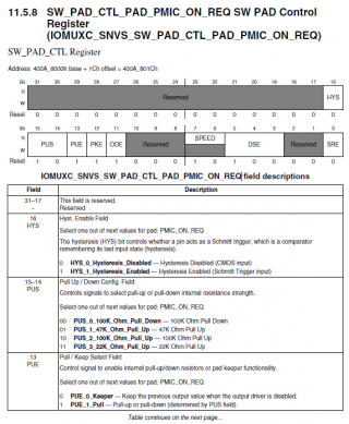
I took a quick search in the processor's manual. I am guessing PMIC_ON_REQ may be some settable pin with pullup or down depending on register/fuse values. Just guessing it provides some pullup to the USB power input pins to enable the processor ONLY if it's connected to either microUSB or VIN, but NOT when 3.3V is supplied to it, correct? What's the reason?
Screenshot 2022-02-01 101600.png
 
It looks like some kind of input telling the processor that 3v3 is being supplied. I don't quite know offhand, but I imagine it's some kind of feature that prevents the teensy from trying to boot if 3v3 isn't active. You'll note a hardware pullup to 3v3 is also included, thought weak at 100k.
It doesn't seem related to USB power, except that the 3V3 is derived from it.

If you'd like to supply 3v3 yourself because you need more than 250mA, simply use your own supply and don't connect to the T's 3v3.
 
The 100k resistor is between the EN pin of the regulator and 3.3V output. So unless PMIC pin can pull EN high, I don't see how this regulator can switch on by itself.
 
My first glance wasn't quite right.
USB_VBUS will power VDD_USB_CAP which through D1 will power VDD_SNVS_IN, which is the bank PMIC_ON_REQ is on, which is pulled up. So eventually the 5V line will enable the 3V3 line, it looks like power sequencing to me. SNVS must be on before any of the other 3v3 lines are powered.
 
Thanks Edward. This all makes sense now. I am guessing VDD_USB_CAP is powered internally by one of the USBn_VBUS pins from the microUSB port. So the diode D1 is just making sure the flow of current in the correct direction against back-filling? And Q1 is just preventing current flowing from board into the microUSB port, right?
 
Yes, it's actually a reasonably elegant way of doing things.

You've got VDD_SNVS_IN which needs to be the first 3v3 (ish, it accepts something like 2-3.5 IIRC) line powered, but the hardware needs to also accept the use of VBAT, which is your battery connection for a real-time clock. So the diodes D1 and D2 provide three options for VDD_SNVS_IN
1) power comes from VBAT, through D2, which means if the external Vin is removed, the VBAT stays just powering the VDD_SNVS, but not keeping the whole chip powered (and draining the battery)
2) power comes from the USB_VBUS, from USB_CAP, through D1 either from Vin or from one of the USB ports, and then
3) PMIC_ON_REQ turns on the 3v3 regulator, which powers VDD_SNVS_IN through D2

The use of diodes means only one of the three will drive the pin, whichever is the highest, which will be the 3v3 regulator (if active). So you can use the battery for RTC applications, but the battery doesn't power the whole 3v3 rail, and once the Teensy gets powered, the 3v3 regulator turns on. Because the 3v3 rail will be higher than the battery, D1 will disconnect the battery.
Q1, exactly as you say, is basically being a low on-resistance diode.
 
Back
Top