Soo, I've designed these universal Teensy 4.1 audio boards.
These boards can be used as drum sequencer, synth, (DJ) effects device, 2ch mixer with pre fader headphone out, 4ch mixer or possibly many other things.
There are several options for controls and audio I/O. You can choose between a variant with a 4x4 grid of 12mm buttons or a 4x4 grid of rotary potentiometers (Alps RK09). For audio I/O, you can choose between [2x audio input, 2x audio output, 1x MIDI in, 1x MIDI out] or [4x audio input, 1x audio output, 1x MIDI out]. In both variants, one line out can be toggled to be a headphone output. ADCs are PCM1808, DACs are CS4344, the headphone amp is a PAM8908.
Version 1:
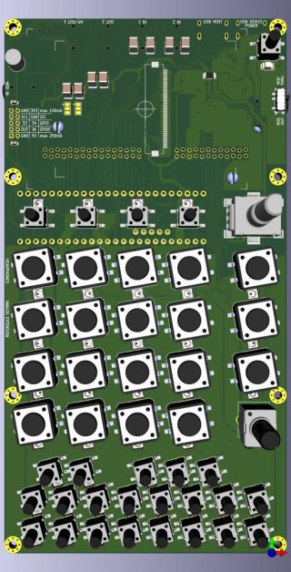
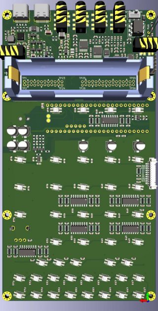
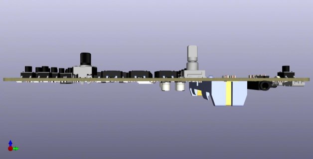
Version 2:
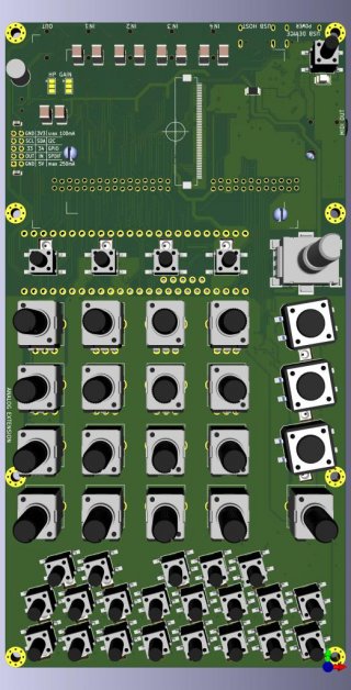
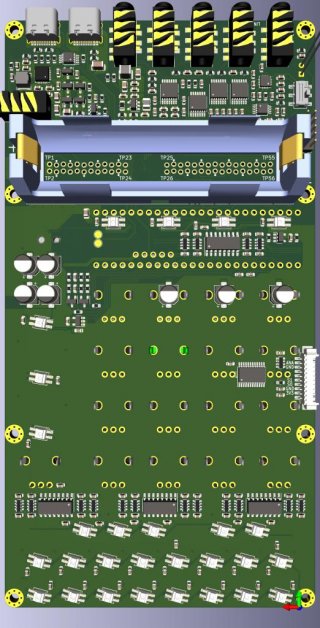
The boards are battery powered (LiIon 18650, TI bq25895, power path management), can act as USB host and device (USB C) and have a 2.8 inch IPS display (not shown in the pictures) with ambient light sensor for automatic brightness control.
The boards also include one volume potentiometer, on push button rotary encoder, 3 large buttons (could be PLAY, REC & SHIFT), and 25 small buttons which are partly arranged in a pattern so they can be used for playing notes or as a step sequencer. Each button also has an adressable RGB LED. The idea is to make PCB front plates with copper cutout symbols where the light can shine through. This way you can easily swap the front plate and use the device for a different function. Buttons are read out by 74HC165 shift registers.
There's also the option to use the I/O header to add an additional board on the back of the device. The I/O header offers 3.3V, 5V, S/DPIF I/O, I2C and GPIO 33+34. The addon board could offer S/PDIF I/O (coaxial and/or optical), CV/GATE (using an I2C module with a MAX11312) or even a built in speaker.
You can also use the analog extension to hook up an additional board via cable. On the board, you can add a 16ch multiplexer for 16 mappable potentiometers, and also extend the chain of addressable LEDs to colorcode the mapping. Both extension variants are independent of the board variants, so you can use every extension board with every main variant.
Most of the parts are listed by LCSC, even though some might need to be bought at different places (you know, the whole chip shortage problem).
All of the ICs are from reputable manufacturers, so you should also be able to buy most of the parts at Mouser or Digikey, only the buttons and audio jacks need to be bought from LCSC.
Some parts that can't be bought at LCSC are: LEDs, battery holder, display, audio film capacitors (PANASONIC ECPU 1µF), pogo pins (for USB) and the SMD rotary encoder.
Hand solderability is mediocre: smallest parts size is 0603, and there are two QFN packages (headphone amp and power), but for testing, you can skip the headphone amp and add a 0 ohm resistor to skip the power circuitry.
All parts on the front side are easy to hand solder (even though the display connector might be a bit tough to solder), so you could also use a SMT service for the backside or solder it with a frying pan and then do the front by hand.
Almost all Teensy pins are also available as test points, the test points have a pitch of 2mm and are staggered, so you can push in a pin header which is then held in place by friction.
Two board variants are 99% routed, the 2in2out with full MIDI and buttons, and the 4in1out with MIDI out and rotary potentiometers. But the other two variants could also be routed pretty easily, as most traces are compatible with all designs.
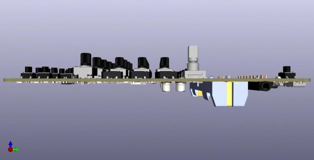
The boards are 4-layer boards, with two GND layers in the middle for better signal integrity. Outer dimensions of the main PCBs is 190x70mm and the 18650 battery tilts the device by 8 degrees, similar to the Teenage Engineering Pocket Operators.
But there's one catch:
I can only do hardware, my understanding of programming is pretty basic. So if anyone is interested and willing, I would be glad to release the design files, so other people can write the code to make this project a real thing.
These boards can be used as drum sequencer, synth, (DJ) effects device, 2ch mixer with pre fader headphone out, 4ch mixer or possibly many other things.
There are several options for controls and audio I/O. You can choose between a variant with a 4x4 grid of 12mm buttons or a 4x4 grid of rotary potentiometers (Alps RK09). For audio I/O, you can choose between [2x audio input, 2x audio output, 1x MIDI in, 1x MIDI out] or [4x audio input, 1x audio output, 1x MIDI out]. In both variants, one line out can be toggled to be a headphone output. ADCs are PCM1808, DACs are CS4344, the headphone amp is a PAM8908.
Version 1:


Version 2:


The boards are battery powered (LiIon 18650, TI bq25895, power path management), can act as USB host and device (USB C) and have a 2.8 inch IPS display (not shown in the pictures) with ambient light sensor for automatic brightness control.
The boards also include one volume potentiometer, on push button rotary encoder, 3 large buttons (could be PLAY, REC & SHIFT), and 25 small buttons which are partly arranged in a pattern so they can be used for playing notes or as a step sequencer. Each button also has an adressable RGB LED. The idea is to make PCB front plates with copper cutout symbols where the light can shine through. This way you can easily swap the front plate and use the device for a different function. Buttons are read out by 74HC165 shift registers.
There's also the option to use the I/O header to add an additional board on the back of the device. The I/O header offers 3.3V, 5V, S/DPIF I/O, I2C and GPIO 33+34. The addon board could offer S/PDIF I/O (coaxial and/or optical), CV/GATE (using an I2C module with a MAX11312) or even a built in speaker.
You can also use the analog extension to hook up an additional board via cable. On the board, you can add a 16ch multiplexer for 16 mappable potentiometers, and also extend the chain of addressable LEDs to colorcode the mapping. Both extension variants are independent of the board variants, so you can use every extension board with every main variant.
Most of the parts are listed by LCSC, even though some might need to be bought at different places (you know, the whole chip shortage problem).
All of the ICs are from reputable manufacturers, so you should also be able to buy most of the parts at Mouser or Digikey, only the buttons and audio jacks need to be bought from LCSC.
Some parts that can't be bought at LCSC are: LEDs, battery holder, display, audio film capacitors (PANASONIC ECPU 1µF), pogo pins (for USB) and the SMD rotary encoder.
Hand solderability is mediocre: smallest parts size is 0603, and there are two QFN packages (headphone amp and power), but for testing, you can skip the headphone amp and add a 0 ohm resistor to skip the power circuitry.
All parts on the front side are easy to hand solder (even though the display connector might be a bit tough to solder), so you could also use a SMT service for the backside or solder it with a frying pan and then do the front by hand.
Almost all Teensy pins are also available as test points, the test points have a pitch of 2mm and are staggered, so you can push in a pin header which is then held in place by friction.
Two board variants are 99% routed, the 2in2out with full MIDI and buttons, and the 4in1out with MIDI out and rotary potentiometers. But the other two variants could also be routed pretty easily, as most traces are compatible with all designs.
The boards are 4-layer boards, with two GND layers in the middle for better signal integrity. Outer dimensions of the main PCBs is 190x70mm and the 18650 battery tilts the device by 8 degrees, similar to the Teenage Engineering Pocket Operators.
But there's one catch:
I can only do hardware, my understanding of programming is pretty basic. So if anyone is interested and willing, I would be glad to release the design files, so other people can write the code to make this project a real thing.

