Avionics CAN-bus monitor

Status
Not open for further replies.

Avatario

Member
Good afternoon,

This is my first post after having followed this great forum for a while. I am reaching out because I would need some help with my new project: I'd like to understand the communication of an avionics device that uses the CAN bus to communicate to a bunch of other avionics devices on an avionics (CAN) bus in order to control it with the help of a Teensy 4.1. So far I've been able to get my T4.1 running some examples enabled by the FlexCAN_T4 library. I can see the output of the avionics device in the log via my serial monitor and I can make some sense out of it.

To get a more comprehensive understanding of the protocol and messages I'd like to use a CAN sniffing tool under Windows now. This tool interfaces CAN sniffers which use the Lawicel CAN/Serial protocol via USB. And here is my question: Is there a piece of software ready to run on a T4.1 that provides this protocol? I am aware of mjs513's CAN Bus monitor (https://github.com/mjs513/Teensy_Canbus_Monitor_IFCT) but it seems to work on a T3.x only.

Thanks very much in advance for your help!
 
Can you post photos of the avionics equipment? Or names and serial numbers? Not many avionics manufacturers using CAN yet, so should be easy enough to figure out with more info.
 
Sorry I wasn't clear enough. The avionics device is a radio and 'speaks' the CANaerospace protocol. But I don't understand the various messages and their semantics yet. With my T4.1 I am already running a CAN bus interface and I can display CAN frames in the serial monitor. What I need now is a more professional tool to analyse and reverse engineer the various CAN messages from the radio. These windows tools use a protocol called CAN ASCII / Serial CAN / SLCAN protocol which is compatible with Lawicel CAN232/CANUSB. There are a couple of projects on Github (https://github.com/latonita/arduino-canbus-monitor or https://github.com/autowp/arduino-canhacker), but they all use the MCP2515 CAN controller. I don't want to go down that route as my T4.1 already has a CAN controller onboard. So I am looking for a port of the Serial CAN protocol to the T4.1, ie a piece of software that provides the Serial CAN protocol on the basis of FlexCAN_T4 or so. Hope that makes sense ...
 
@BriComp got me curious whether I could port the CanBus monitor over to the T4.x. So gave it try and it seems to be working. I only implemented the CAN-232 piece and not the MCP_CAN since you may want to use it without using a MCP2515 shield which it was designed for. Unfortunately, at the moment can't set it up to give it a full test but maybe later today.

In the meantime if anyone wants to give it a try I am attaching the sketch.
 

Attachments

  • Teensy-CanBus-Monitor.zip
    9.1 KB · Views: 95
Thanks brtaylor, I am aware of the spec. My device complies with the type definitions in the CAN aerospace protocol, but uses custom message IDs I need to better understand.
 
@BriComp got me curious whether I could port the CanBus monitor over to the T4.x. So gave it try and it seems to be working. I only implemented the CAN-232 piece and not the MCP_CAN since you may want to use it without using a MCP2515 shield which it was designed for. Unfortunately, at the moment can't set it up to give it a full test but maybe later today.

In the meantime if anyone wants to give it a try I am attaching the sketch.

Thanks mjs513, I'll give it a try.
 
@BriComp got me curious whether I could port the CanBus monitor over to the T4.x. So gave it try and it seems to be working. I only implemented the CAN-232 piece and not the MCP_CAN since you may want to use it without using a MCP2515 shield which it was designed for. Unfortunately, at the moment can't set it up to give it a full test but maybe later today.

In the meantime if anyone wants to give it a try I am attaching the sketch.

Have tried this. It compiles and runs on a T4.1. My Windows Software 'CANHacker' starts, connects, delivers some CAN messages, and quickly disconnects again. When I try to re-connect again, it throws 'CAN Interface is not responding'. But thanks anyway!
 
Have tried this. It compiles and runs on a T4.1. My Windows Software 'CANHacker' starts, connects, delivers some CAN messages, and quickly disconnects again. When I try to re-connect again, it throws 'CAN Interface is not responding'. But thanks anyway!

ok had some time today so I reworked the monitor - I think its working at this point but still need to do a few things to make it perfect. It defaults to 1000kps and can3. CAN bus can be changed in the can-232.cpp file - hopefully will figure out a way to make it declarable. If you can give it a try and let me know if it works any better would be appreciated :)

UPDATE: I edited the sketch a bit more so this should be work - i did test sending and receiving so hope it helps you.
View attachment Teensy-CanBus-Monitor-220215a.zip
 
Last edited:
@Avatario - @brtaylor - @bricomp

I made a few more changes to the can-232 library and seems to be working much better. Again default Can bus is 1000000mhz and uses CAN3 on a T41 - if you want to change this you will have to edit the can-232.cpp file. I also added an extra command ('.') - that if you send it will print out the mb info in expanded format. I did test it with the pub.ino sketch for drone can and the Can2.0_example_FIFO with interrupts sketch and it seems to be working correctly at this point.

From the Pub.ino sketch:
Code:
+T10015502800000000080000C0
+T1003FC02500000000C0
+T1003FC025003C0000C1
+T1003FC02500400000C2
+T1003FC02500420000C3
+T1003FC02500440000C4
+T1003FC02500450000C5
+T1003FC02500460000C6
+T1003FC02500470000C7
+T1003FC02500480000C8
+T10015502801000000000000C1
+T1003FC02580480000C9
+T1003FC02500490000CA
+T1003FC02580490000CB
+T1003FC025004A0000CC
+T1003FC025804A0000CD
+T1003FC025004B0000CE
+T1003FC025804B0000CF
+T1003FC025004C0000D0
+T1003FC025404C0000D1
+T1003FC025804C0000D2
+T10015502802000000000000C2
....
 ID: 1003FC02  OVERRUN: 0  LEN: 5 EXT: 1 RTR: 0 TS: 46151 Buffer: 40 4D 0 0 D9 
+T1003FC025404D0000D9
 ID: 1003FC02  OVERRUN: 0  LEN: 5 EXT: 1 RTR: 0 TS: 15207 Buffer: 80 4D 0 0 DA 
+T1003FC025804D0000DA
 ID: 1003FC02  OVERRUN: 0  LEN: 5 EXT: 1 RTR: 0 TS: 49799 Buffer: C0 4D 0 0 DB 
+T1003FC025C04D0000DB
 ID: 1003FC02  OVERRUN: 0  LEN: 5 EXT: 1 RTR: 0 TS: 18854 Buffer: 0 4E 0 0 DC 
+T1003FC025004E0000DC
 ID: 10015502  OVERRUN: 0  LEN: 8 EXT: 1 RTR: 0 TS: 53447 Buffer: 13 0 0 0 0 0 0 D3 
+T10015502813000000000000D3
 ID: 1003FC02  OVERRUN: 0  LEN: 5 EXT: 1 RTR: 0 TS: 53597 Buffer: 40 4E 0 0 DD 
+T1003FC025404E0000DD
 ID: 1003FC02  OVERRUN: 0  LEN: 5 EXT: 1 RTR: 0 TS: 22569 Buffer: 80 4E 0 0 DE 
+T1003FC025804E0000DE

Using the Flexcan_T4 example sketch:
Code:
+t66280102030405060708
+t03680102030405060708
+t38980102030405060708
+t69D80102030405060708
+t00780102030405060708
+t7B980102030405060708
+t5DA80102030405060708
+t3E280102030405060708
+t38E80102030405060708
+t10A80102030405060708
+t71E80102030405060708
+t5BE80102030405060708
+t48780102030405060708
Command received:.

 ID: 7AD  OVERRUN: 0  LEN: 8 EXT: 0 RTR: 0 TS: 14289 Buffer: 1 2 3 4 5 6 7 8 
+t7AD80102030405060708
 ID: 3FE  OVERRUN: 0  LEN: 8 EXT: 0 RTR: 0 TS: 18678 Buffer: 1 2 3 4 5 6 7 8 
+t3FE80102030405060708
View attachment Teensy-CanBus-Monitor-220215a.zip
 
I am happy to help to test the functionality.

Ok you asked for it. This a rough cut on a standalone FD version I was working on today. It is receiving FD messages and seems to be able to still send at least I didn't break that part of it. At some point I would like to combine the two into one lib that supports both but figured this might be easier as a first cut. What doesn't work is changing rates with the S command.

Here is a old test sketch that I used when testing CANFD a long time ago:
Code:
#include <FlexCAN_T4.h>
FlexCAN_T4FD<CAN3, RX_SIZE_256, TX_SIZE_16> FD;

uint32_t CLOCK = 20000000;

void setup(void) {
  Serial.begin(115200); delay(500);
  pinMode(6, OUTPUT); digitalWrite(6, LOW);
  FD.begin();
  FD.setRegions(32);
  FD.setBaudRate(CAN_1M_2M);
  Serial.println("\n\n\n\n");
}
bool sett = 1;
void loop() {

  CANFD_message_t msg;
  msg.len = 16; msg.id = 0x321;
  msg.flags.extended = 0;
  msg.buf[0] = 1; msg.buf[1] = 2; msg.buf[2] = 3; msg.buf[3] = 4;
  msg.buf[4] = 5; msg.buf[5] = 6; msg.buf[6] = 9; msg.buf[7] = 9;
  msg.buf[8] = 1; msg.buf[9] = 2; msg.buf[10] = 3; msg.buf[11] = 4;
  msg.buf[12] = 5; msg.buf[13] = 6; msg.buf[14] = 9; msg.buf[15] = 9;
  FD.write( msg);

  if ( FD.read(msg) ) {
    bool prnt = 1;
    if ( prnt ) {
      Serial.print("MB: "); Serial.print(msg.mb);
      Serial.print("  OVERRUN: "); Serial.print(msg.flags.overrun, HEX );
      Serial.print("  ID: 0x"); Serial.print(msg.id, HEX );
      Serial.print("  EXT: "); Serial.print(msg.flags.extended );
      Serial.print("  LEN: "); Serial.print(msg.len);
      Serial.print(" DATA: ");
      for ( uint8_t i = 0; i < msg.len; i++ ) {
        Serial.print(msg.buf[i]); Serial.print(" ");
      }
      Serial.print("  TS: "); Serial.println(msg.timestamp);
    }
  }

  delay(25);
  msg.id = 0x1;
  msg.len = 8;  msg.flags.extended = 0;
  FD.write( msg);
  delay(25);
  
  msg.id = 0x4;
  msg.len = 16;    msg.flags.extended = 0;
  FD.write( msg);
  delay(25);
  
  msg.id = 0x2;
  msg.len = 16;    msg.flags.extended = 0;
  FD.write( msg);
  delay(25);
  
  msg.id = 0x08;
  msg.len = 16; msg.flags.extended = 0;
  FD.write( msg);
  delay(25);
  
    msg.id = 0x1E;
    msg.flags.extended = 1;
  msg.len = 16; 
  FD.write( msg);
  delay(25);
  
  msg.id = 0x3;
  msg.flags.extended = 0;
  msg.len = 16; 
  FD.write( msg);
  delay(25);
}

Here is the FD Lib:
View attachment Teensy_Canbu_Monitor_FlexcanFD.zip
 
Had a quick play.

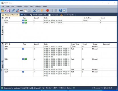
On receiving a CAN FD frame, it prints out txxxx but can't tell whether the CAN FD frame has the BRS flag set or not. Maybe a different letter then 't'.

On transmitting a CAN FD frame, its need the option of the CAN FD frame has BRS flag set or not. It can't transmit with more then 8 bytes at the moment.

I'm using the PCAN-USB Pro FD analyzer from Peak-System.
192_168_1_28.jpg
 
Took a bit but think I got it all working now (at least for the most part). Fixed T and t commands so can send more than 8 bytes, however, when sending the length you you have to put 8 in as 08 to make it work correctly. Here is the command summary:
Code:
//                          CODE   SUPPORTED   SYNTAX               DESCRIPTION     
//
[COLOR="#FF0000"]#define LW232_CMD_SETUP     'S' //   YES+      Sn[CR]               Setup with standard CAN bit-rates where n is 0-8.
                                //                                  S0 CAN_1M_2M
                                //                                  S1 CAN_1M_4M
                                //                                  S2 CAN_1M_6M
                                //                                  S3 CAN_1M_8M[/COLOR]
#define LW232_CMD_SETUP_BTR 's' //    -        sxxyy[CR]            Setup with BTR0/BTR1 CAN bit-rates where xx and yy is a hex value.
#define LW232_CMD_OPEN      'O' //   YES       O[CR]                Open the CAN channel in normal mode (sending & receiving).
#define LW232_CMD_LISTEN    'L' //   YES       L[CR]                Open the CAN channel in listen only mode (receiving).
#define LW232_CMD_CLOSE     'C' //   YES       C[CR]                Close the CAN channel.
[COLOR="#FF0000"]#define LW232_CMD_TX11      't' //   MOD       tiiilldd...[CR]       Transmit a standard (11bit) CAN frame.
#define LW232_CMD_TX29      'T' //   MOD       Tiiiiiiiilldd...[CR]  Transmit an extended (29bit) CAN frame
#define LW232_CMD_RTR11     'r' //   NO        riiil[CR]            FD no support Remote Frames. Transmit an standard RTR (11bit) CAN frame.
#define LW232_CMD_RTR29     'R' //   NO        Riiiiiiiill[CR]      FD no support Remote Frames. Transmit an extended RTR (29bit) CAN frame.[/COLOR]
#define LW232_CMD_POLL_ONE  'P' //   YES       P[CR]                Poll incomming FIFO for CAN frames (single poll)
#define LW232_CMD_POLL_MANY 'A' //   YES       A[CR]                Polls incomming FIFO for CAN frames (all pending frames)
#define LW232_CMD_FLAGS     'F' //   YES+      F[CR]                Read Status Flags.
#define LW232_CMD_AUTOPOLL  'X' //   YES       Xn[CR]               Sets Auto Poll/Send ON/OFF for received frames.
#define LW232_CMD_FILTER    'W' //    -        Wn[CR]               Filter mode setting. By default CAN232 works in dual filter mode (0) and is backwards compatible with previous CAN232 versions.
#define LW232_CMD_ACC_CODE  'M' //    -        Mxxxxxxxx[CR]        Sets Acceptance Code Register (ACn Register of SJA1000). // we use MCP2515, not supported
#define LW232_CMD_ACC_MASK  'm' //    -        mxxxxxxxx[CR]        Sets Acceptance Mask Register (AMn Register of SJA1000). // we use MCP2515, not supported
#define LW232_CMD_UART      'U' //   YES       Un[CR]               Setup UART with a new baud rate where n is 0-6.
#define LW232_CMD_VERSION1  'V' //   YES       v[CR]                Get Version number of both CAN232 hardware and software
#define LW232_CMD_VERSION2  'v' //   YES       V[CR]                Get Version number of both CAN232 hardware and software
#define LW232_CMD_SERIAL    'N' //   YES       N[CR]                Get Serial number of the CAN232.
#define LW232_CMD_TIMESTAMP 'Z' //   YES+      Zn[CR]               Sets Time Stamp ON/OFF for received frames only. EXTENSION to LAWICEL: Z2 - millis() timestamp w/o standard 60000ms cycle
#define LW232_CMD_AUTOSTART 'Q' //   YES  todo     Qn[CR]               Auto Startup feature (from power on). 
[COLOR="#FF0000"]#define LW232_CMD_CUSTOM    '.' // custom to turn MB details on/off
#define LW232_CMD_BRS		'B' // toggles BRS bit on and off, defaults to 1.[/COLOR]
Changes are highlighted in RED

Remember to see plain english use the '.' command while receiving data

For now here is the library:View attachment Teensy_Canbu_Monitor_FlexcanFD.zip
 
Status
Not open for further replies.
Back
Top