Built-in vs. external DAC for oscilloscope graphics

achy

New member
Hi everyone,

I've been working on a library that allows drawing 2D/3D graphics on oscilloscopes: https://github.com/achydenius/voltage. The library is currently using the dual DAC of Teensy 3.6 for sending suitable voltage to the oscilloscope's X and Y axis inputs. The values written are defined by tracing the lines with a standard line drawing algorithm. In order to achieve a flicker-free image, the oscilloscope has to be constantly sent data as fast as possible.

I've done some performance profiling and it seems that the drawing and especially the DAC writes are the clear bottleneck. I've already done some optimizations, e.g. inlining the DAC write calls, but the amount of geometry that can be drawn without flickering feels still a bit limited. The Teensy 4.x series would be otherwise perfect for the task, but they lack the built-in DAC. I've seen people using external SPI DACs with Teensy 4, but I was still wondering if it solves the performance problem – I assume then the speed of the SPI bus might be a limiting factor? I've had a bit hard time finding some exact information about the DAC frequencies, bus speeds, etc. so if anyone here has an insight on these, I'd be super grateful.

Thanks!

(edit: Just noticed that the Project Guidance forum might have been a more relevant place for the question, but I hope it reaches people here as well :))
 
You've tried adjusting the 'scope timebase? In XY mode you normally have to do this - and you
probably won't get completely flicker-free operation on most digital scopes in XY mode as they
acquire/display/acquire/display in sequence as the sample memory isn't dual-ported (much
more expensive).

SPI DACs with 500kSPS or so are pretty easy to find (though with current chip shortages that
might not be the case I guess) - for faster operation the interface is more likely to be parallel
than SPI. Expect modern devices to handle 16 to 30MHz max SPI speeds or so, so 500kSPS
should be straightforward to drive on a T4 without having to resort to DMA.

Normally 8 bit is enough for a 'scope.
 
Hi,
I'm using a T3.6 with quad audio shields and both DAC GPIOs to simultaneously generate 14 sine waveforms, ranging from 100Hz-600Hz. But, my oscilloscope is unable to refresh fast enough and has residual luminosity, so it doesn't accurately display the x/y imagery.
My problem is that the audio shields have capacitors on the line outputs, which block DC offsets, which I need for laser beam positioning. On the other hand, the 2 GPIO DACs have no capacitors on the outputs, which is good, except for their own inherent DC offsets. Trying to compensate with software only produces clipping at 0 VDC.
Hope this info is helpful.
 
You do realize DACs cannot normally generate voltages outside their supply range?

There are some I2S DACs that have on-chip inverters that generate a -ve internal supply - that's what you need for
zero-centred DC output (assuming the high-pass filters can be disabled on the chip - many I2S DACs have high pass filters
specifically to remove DC - DC is very bad for speakers).
Yes. That's why the GPIO DACs can only output between 0 and ~ 2 VDC. But, the T3.x audio shields have capacitors on their line outputs, which block DC offsets and center the signal around 0 VDC.
My primary point to achy is that I'm not experiencing any bottlenecks with generating very complex vector lissajous imagery with the T3.6.
As a laserist (and possibly for Achy, as well). DC offsets are important and even desirable for beam/imagery positioning and DC controlled color. That's why I wanted to inform him/her of my findings. So, my problem is finding suitable DC coupled DACs or finding someone who can tell me how to modify the T3.x audio shields to eliminate the capacitors.
I've already tried shorting across the caps and have successfully destroyed 3 out of 3 T3.x Audio Shields.
I'm open to any suggestions from anyone who knows of a solution.
BR
:cool:
 
You've tried adjusting the 'scope timebase? In XY mode you normally have to do this - and you
probably won't get completely flicker-free operation on most digital scopes in XY mode as they
acquire/display/acquire/display in sequence as the sample memory isn't dual-ported (much
more expensive).

SPI DACs with 500kSPS or so are pretty easy to find (though with current chip shortages that
might not be the case I guess) - for faster operation the interface is more likely to be parallel
than SPI. Expect modern devices to handle 16 to 30MHz max SPI speeds or so, so 500kSPS
should be straightforward to drive on a T4 without having to resort to DMA.

Normally 8 bit is enough for a 'scope.

I'm using only analog oscilloscopes since I'm after the visual quality of some vector graphics coin-op games of the 80s (Star Wars, Battlezone and such). After experimenting with different bit depths, it seems that 10-12 bits yield visually smooth lines where individual beam plots can't be seen. Btw, an example video of the system in action can be found here: https://www.facebook.com/1278315233/videos/1139636483488661/.

Any idea which SPI DACs people have been using successfully with Teensy?
 
You do realize DACs cannot normally generate voltages outside their supply range?

There are some I2S DACs that have on-chip inverters that generate a -ve internal supply - that's what you need for
zero-centred DC output (assuming the high-pass filters can be disabled on the chip - many I2S DACs have high pass filters
specifically to remove DC - DC is very bad for speakers).

Yeah, I think the Teensy 3.3V output is okay, since it's always possible to scale the values with the voltage divider of the oscilloscope.
 
Yes. That's why the GPIO DACs can only output between 0 and ~ 2 VDC. But, the T3.x audio shields have capacitors on their line outputs, which block DC offsets and center the signal around 0 VDC.
My primary point to achy is that I'm not experiencing any bottlenecks with generating very complex vector lissajous imagery with the T3.6.
As a laserist (and possibly for Achy, as well). DC offsets are important and even desirable for beam/imagery positioning and DC controlled color. That's why I wanted to inform him/her of my findings. So, my problem is finding suitable DC coupled DACs or finding someone who can tell me how to modify the T3.x audio shields to eliminate the capacitors.
I've already tried shorting across the caps and have successfully destroyed 3 out of 3 T3.x Audio Shields.
I'm open to any suggestions from anyone who knows of a solution.
BR
:cool:

Why not try a fairly good op-amp circuit, you could easily apply a DC offset to the opposite input to offset the output to just about any voltage you like. This is a trivial circuit to implement and if designed correctly could be a very small circuit board you could piggy-back on the teensy audio board, or use after the output capacitors in your circuit.

Regards,
Ed
Thank you for that suggestion, Ed. Yes, I've considered that option, but I'm far from being an EE. In fact, last week, I put together my 1st 2 X gain buffer to provide a high impedance output for the audio shield that I had replaced the caps on. Prior to that test, I was only getting a small signal with lots of noise. With the buffer, I only had noise on the amp's input and 2 X noise on its output. Success?
Regarding your suggestion, I found some inexpensive Adafruit quad DACs that can generate lower frequency waveforms and DC offsets via I2C. Theoretically, I could sum those outputs with the T3.x audio shield outputs to achieve my objective.... except their I2C addresses conflict. Apparently, there are some quad DACs on AliExpress that can be special ordered with different I2C addresses. That might be my final string to grasp for.
On a personal note to achy, here's the DC coupled I2C quad DAC from Adafruit that I've tested:
https://learn.adafruit.com/adafruit-mcp4728-i2c-quad-dac/arduino
Also, have you considered using an RGB laser projector for your project, instead of an oscilloscope? They are now less expensive than a good 'scope @ ~ $300 for a 1 watt RGB projector. Here's an example of what I'm shooting for (by a GOAT laserist, named Christopher Short):https://www.youtube.com/watch?v=jSJ09fe-yQE&list=RDMM&index=25
 
Last edited:
Thank you for that suggestion, Ed. Yes, I've considered that option, but I'm far from being an EE. In fact, last week, I put together my 1st 2 X gain buffer to provide a high impedance output for the audio shield that I had replaced the caps on. Prior to that test, I was only getting a small signal with lots of noise. With the buffer, I only had noise on the amp's input and 2 X noise on its output. Success?
Regarding your suggestion, I found some inexpensive Adafruit quad DACs that can generate lower frequency waveforms and DC offsets via I2C. Theoretically, I could sum those outputs with the T3.x audio shield outputs to achieve my objective.... except their I2C addresses conflict. Apparently, there are some quad DACs on AliExpress that can be special ordered with different I2C addresses. That might be my final string to grasp for.
On a personal note to achy, here's the DC coupled I2C quad DAC from Adafruit that I've tested:
https://learn.adafruit.com/adafruit-mcp4728-i2c-quad-dac/arduino
Also, have you considered using an RGB laser projector for your project, instead of an oscilloscope? They are now less expensive than a good 'scope @ ~ $300 for a 1 watt RGB projector. Here's an example of what I'm shooting for (by a GOAT laserist, named Christopher Short):https://www.youtube.com/watch?v=jSJ09fe-yQE&list=RDMM&index=25

Hermit:
In your first sentence I think you meant to provide a low impedance output for the audio shield as Op-amps generally have high impedance input and low impedance outputs. Generally a gain of two for the first stage is not a very good trade-off, but depending on your goal it is basically operating as an impedance converter with a little bit of voltage gain. It can also act to condition the output in many different ways including adding the offset you seemed to require.

I have seen so many horribly thrown together circuits on this blog as well as others, and it is remarkable that some of them even work. It shows how flexible modern electronics circuits are. As I have always maintained "The devil is in the details".

I am fairly certain that the Teensy 3.x has more than 1 I2C outputs so if there is a conflict just put the conflicting parts on another I2C bus, but don't forget to install the pull-up resistors.

Regards,
Ed
 
Hi everyone,

I've done some performance profiling and it seems that the drawing and especially the DAC writes are the clear bottleneck. I've already done some optimizations, e.g. inlining the DAC write calls, but the amount of geometry that can be drawn without flickering feels still a bit limited. The Teensy 4.x series would be otherwise perfect for the task, but they lack the built-in DAC. I've seen people using external SPI DACs with Teensy 4, but I was still wondering if it solves the performance problem

Are you referring to the T4.x audio shield, with stereo DAC line outputs, which receives its audio signals via I2S protocol? That's what I've been using with multiple waveforms being generated by the audio library. I2S is optimized for streaming audio and much faster than I2C. Haven't seen any SPI DACs on the market.
Looking at your code, I'm wondering why it is using rasterization functions for vector imagery on an x/y scope? On the other hand, I've been looking for info on how to display my vector imagery onto a 7" TFT display. Thank you for opening that door of knowledge within your links.
 
Thank you for the helpful feedback, Ed.
Time for a broader picture to my situation. I need at least 5 DAC outputs for XYRGB signals to control my laser imagery. The T3.6 + quad audio shields + 1 GPIO DAC works, except for the audio shields' capacitors blocking DC offsets and the inherent 1.5 DC offsets, which are caused by the 0-3 VDC range of the T3.6's GPIO DACs.
I saw another laserist mention replacing the line output capacitors (with PC sound cards) to provide DC coupling. So, I tried it and fried 2 audio shields. Then, I assumed that there needed to be some impedance to protect the DACs from over current and put together the op-amp buffer, as a high impedance connection to the DACs. I already had some TL074 op-amps and got the circuit from an online electronics document. The 2 x gain was just an added feature to boost the DAC's output from 3 volts to 5 volts for my projector's driver boards.
As previously mentioned, previous tests on that audio shield produced lots of noise and a faint signal on my o'scope. I now suspect that was it's final effort, before dying as I saw with the op-amp test.
Perhaps I could bridge the output caps and immediately apply a high impedance op-amp buffer, without any possibilities of shorting the signals to grounds? Dare I risk sacrificing another $17 audio shield to find out?
Yes, the T3.6 has several I2C pins, but the Teensy audio shields only have hardwired I2C addresses of 0x60 and 0x62 for the second quad board, same as Adafruit's I2C quad DAC boards.

Hermit:
I think I did not make myself clear concerning I2C Busses. If there is a conflict using one of the I2C busses, I suggested to use another BUS! (That is Wire, or Wire1, or Wire2), then the conflict goes away. This will only work if the bus pins for Wire1 or Wire2 are not being used for something else. Just look at the card that came with the Teensy and it will give you the pins with the other I2C busses.

I would also suggest that you study the data sheet carefully for the SGTL5000 before you try any more messing around with the output capacitors of the Teensy Audio Shields. I know that the headphone output has an artificial ground created on the chip that cannot be tied to ground or it will blow up the chip.

At this point I don't think I can help you any more unless you provide a complete schematic of your circuit, otherwise I am just shooting in the dark.

Regards,
Ed
 
Are you referring to the T4.x audio shield, with stereo DAC line outputs, which receives its audio signals via I2S protocol? That's what I've been using with multiple waveforms being generated by the audio library. I2S is optimized for streaming audio and much faster than I2C. Haven't seen any SPI DACs on the market.
Looking at your code, I'm wondering why it is using rasterization functions for vector imagery on an x/y scope? On the other hand, I've been looking for info on how to display my vector imagery onto a 7" TFT display. Thank you for opening that door of knowledge within your links.

Hmm, I wasn't even aware of the I2S interface. I did some experimenting with I2C-connected MCP4725 DAC, but that was way too slow for my purposes. Thanks for letting me know there's one more faster alternative available!

Regarding the rasterization, there are few other projects using the same method. If you're interested, here's a more thorough explanation, for example: https://www.nutsvolts.com/magazine/article/tgi-the-teensy-graphics-interface.
 
Ed,
I apologize for not understanding what you are suggesting. I have no prior experience with altering the I2C bus and am only aware that the addresses can't conflict, unless something like an I2C multiplexer or shield are being used. providing their own I2C buses. Yes, I'm aware of the multiple I2C GPIOs on the T3.6, but wasn't aware that they had their own separate buses that could support similar addresses. I have spent many hours studying the datasheets for both, the T3.6 & audio shields, but haven't noticed this being stated.
I've only used the Wire library. Are you saying that it only applies to my current bus and Wire1 enables a different I2C bus, using the alternate GPIOs? IOW, leave the audio shields as they are, then connect the Adafruit DAC's I2C pins to SDA1 & SCL1 on the unused T3.6 pins 37 & 38?
I currently have no circuit designs, because that's what I've been searching for. I only have T3.6s with stacked audio shields. I've only attempted to replace the capacitors with wires (just because that had been mentioned in a laserist forum) Assuming that I had destroyed the DACs, due to no current limiting, I tried adding the simple op-amp circuit, with a few resistors. So, now I'm back to square #1.
With the benefit of the info that you have provided, I can abandon that pursuit and focus on adding the DC coupled Adafruit quad DAC board on a different bus, then use a summing amp to combine those signals with those from the audio shields, right? Sounds like a promising solution. I already have the parts, but obviously need to learn more about the Wire libraries.

Thank you for your time, patience, and explanation, Ed.
BR
:cool:
 
Last edited:
Hi Achy,
LOL! I tested the quad version of the MCP4725, the MCP4788. Yes, I2C is too slow for our applications,,, except slow and DC are exactly what I need. So, thanks to Ed's feedback, I'll be summing both outputs together in order to have both.
BTW, it was our 'pal', Dave's Teensy Synth tutorial series that provided the foundation for my Teensy laser synth project. I did laser shows throughout the 1980s, before changing careers. But, I never lost the enthusiasm for the artform. With today's gear being 1/10 the $, 4 X the capabilities, and Christopher Short's inspirational videos, I couldn't help getting back into the technical artform. Our pal Dave has been a vital part of that journey.,, and still is. Just last night, I was reviewing his content.
 
Ed,
I apologize for not understanding what you are suggesting. I have no prior experience with altering the I2C bus and am only aware that the addresses can't conflict, unless something like an I2C multiplexer or shield are being used. providing their own I2C buses. Yes, I'm aware of the multiple I2C GPIOs on the T3.6, but wasn't aware that they had their own separate buses that could support similar addresses. I have spent many hours studying the datasheets for both, the T3.6 & audio shields, but haven't noticed this being stated.
I've only used the Wire library. Are you saying that it only applies to my current bus and Wire1 enables a different I2C bus, using the alternate GPIOs? IOW, leave the audio shields as they are, then connect the Adafruit DAC's I2C pins to SDA1 & SCL1 on the unused T3.6 pins 37 & 38?
I currently have no circuit designs, because that's what I've been searching for. I only have T3.6s with stacked audio shields. I've only attempted to replace the capacitors with wires (just because that had been mentioned in a laserist forum) Assuming that I had destroyed the DACs, due to no current limiting, I tried adding the simple op-amp circuit, with a few resistors. So, now I'm back to square #1.
With the benefit of the info that you have provided, I can abandon that pursuit and focus on adding the DC coupled Adafruit quad DAC board on a different bus, then use a summing amp to combine those signals with those from the audio shields, right? Sounds like a promising solution. I already have the parts, but obviously need to learn more about the Wire libraries.

Thank you for your time, patience, and explanation, Ed.
BR
:cool:

Hermit:
I think you have finally got it! Yes the Teensy 3.6 has 4 separate I2C busses (I don't have one the T3.6 pinout cards in front of me). Each one is declared separately:
#include <Wire.h>

Wire.begin();
Wire1.begin();
Wire2.begin();
Wire3.begain();

I would recommend you read the I2C stuff at the PJRC website, as well as these pages: https://forum.pjrc.com/threads/21680-New-I2C-library-for-Teensy3,
https://github.com/TeensyUser/doc/wiki/I2C These pages should give you more info concerning I2C use. If you still have questions about I2C the Forum is filled with brilliant minds concerning these matters.

Regards,
Ed
 
Hermit:
I think you have finally got it! Yes the Teensy 3.6 has 4 separate I2C busses (I don't have one the T3.6 pinout cards in front of me). Each one is declared separately:
#include <Wire.h>
Wire.begin();
Wire1.begin();
Wire2.begin();
Wire3.begain();

I would recommend you read the I2C stuff at the PJRC website, as well as these pages: https://forum.pjrc.com/threads/21680-New-I2C-library-for-Teensy3,
https://github.com/TeensyUser/doc/wiki/I2C These pages should give you more info concerning I2C use. If you still have questions about I2C the Forum is filled with brilliant minds concerning these matters.

Regards,
Ed


Thank you for the guidance, Ed. The code example and pointers are exactly what I need to push forward.
Are you not one of those brilliant minds on this forum?
I sincerely appreciate your assistance. This hurdle has been a major obstacle in completing my laser synth project. The code for the waveform generators and MIDI control functionality is already up and running. The projectors are only waiting for some ILDA standard conversion amps to arrive, which will complete the initial hardware. I'e already started on a custom T4.1 MIDI laser control desk. Then, I can get on with creating the actual laser art. Woo Hoo!
Thanks again, Ed
BR
The Hermit
 
Hermit:
Probably not brilliant, but certainly experienced with 2/3rd of Century of experience. If you turn over your cell phone and look at the Camera and realize I worked on the Team that invented the technology that made that possible over 40 years ago. Yes, life has been fun for a 72 year old NERD.

Regards,
Ed
Cool! I'm not very brilliant, either. But, in 1978, I was one of the 2 first laserists to open Laserium at the London Planetarium, then spent the following ten years developing show projection systems. But, I always left the schematics to the engineers. Now, I'm just a retired, bored, old fart/wannabe maker trying to have a little innocent fun, playing with pretty laser patterns in my living room. Keeps me out of mischief and broke.
BR
:cool:
 
Hi Ed,
Just wanted circle back to let you know that yes, thanks to your guidance, I got it. Mission accomplished & I'm happy camper, until the next obstacle comes along, as they inevitably do on ambitious projects such as this.
But, now I still have the I2S quad audio shields outputting the primary waveforms, plus the I2C Adafruit MCP4728 quad DACs handling the DC levels for beam positions and RGB intensities. Now, the quad pairs only need to be summed together.
The ILDA compliant differential amp boards are due to arrive next week. Their input circuits appear to be exactly the same as a summing op amp, So, I should be able to simply add a resistor to the second input and connect in parallel with the existing input's resistor.
Then, I only need to assemble all of the bits to have a fully functional laser show system, just because it's fun.
Thank you again for making an old man happy, Ed
Best regards,
TheHermit
 
Hmm, I wasn't even aware of the I2S interface. I did some experimenting with I2C-connected MCP4725 DAC, but that was way too slow for my purposes. Thanks for letting me know there's one more faster alternative available!

Regarding the rasterization, there are few other projects using the same method. If you're interested, here's a more thorough explanation, for example: https://www.nutsvolts.com/magazine/article/tgi-the-teensy-graphics-interface.

Hi Achy,
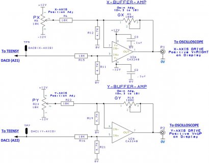
Actually, yes, your link was very interesting. In fact, I was looking for a circuit to correct for the T3.6 DACs' offsets and to double the signal level. Voila'! there it is!
Teensy 3.6 DAC correction circuit.jpg
Also, I'll soon need to figure out how to rotate laser vector imagery around all 3 axis. Looks like your link pointed me to an article for that, as well. Now, I only need to learn some college level geometric equations.
Thanks, Achy!
I hope your project is going well.
Best regards,
TheHermit
:cool:

dit: Oh yeah, just remembered. "Our pal Dave" has a YT Teensy Synth tutorial channel called 'Notes and Volts', not 'Nuts and Volts' from your link. I ws like, "Wow, I never knew that Dave did vector graphics, too. My bad.
 
Back
Top