Project Advice For RA8875 SPI & Teensy 4.1

rmills

Active member
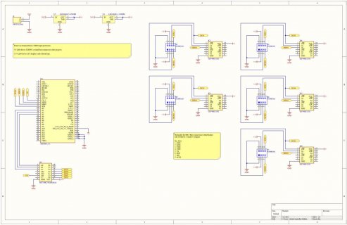
Working on a board that will drive at least 5 displays via 4-wire SPI from a Teensy 4.1. The displays have the RA8875 chipset. I'm more of a software guy than a hardware guy and could use application advice. I attached my starting schematic below, its missing pull resistors, caps, ect but show the basics. The goal of the project is to push different bitmaps to each of the screens based on button pushes. I have been reading up on Paul's dive into the SPI implementation on the RA8875 and since I plan to add an SD card via SPI in the future it sounds like some extra work is required.

For my question, I have not worked with buffers before, the 74HC125 is recommended in everything I read but since it only has 4 elements it's not ideal for my application. I don't understand the root issue well enough to substitute it. I also could not find an example of how you might chain them so I could use 2, if that is even possible. I did find an example using one per screen and that's what I'm using at the moment. Is it possible to chain up two 74HC125's instead using five? Or is there another common buffer better suited to 6 or more elements? Second, to save ports I added a multiplexer for the CS. Will that cause any timing issues with the SCLK timing?


Display: https://www.buydisplay.com/5-inch-tft-lcd-module-800x480-display-controller-i2c-serial-spi
Schematic:
 

Attachments

  • SolarController.jpg
    SolarController.jpg
    98.9 KB · Views: 32
Last edited:
rmills:
Where should I start, there are so many problems with this design it's difficult to even start.
1. Why are you using 5 different quad Tri-state buffers. Don't you know the there are 4 individual independent buffers in each package? Each one's output is individually controlled by its tri-state input pin.
You could easily get away with only two of the buffers with a couple spares. The only pin that absolutely has to have a tri-state buffer is the MISO pin from each RA8875, and tri-state control pin is
driven by the CS/ signal for each RA8875. I would use two of the spares as an input buffer for MOSI, and an output buffer for the clock as you will probably need the extra current driving capacity to
drive all the stray capacitance of the wires for the 5 RA8875 displays.

2. If you are planning to use the RA8875 drivers from the Teensy library then you will not be able to use the MUX in your schematic without rewriting those libraries.

3. I am also sure you need at least one or two more signals to drive these displays with these libraries. Consult the library you plan on using for the extra pins this display uses.

4. I would also not use the 74HC125, but would chose the 74AHCT125 as it is much faster and the RA8875 can take clock speeds up to about 18MHz depending on the length of the wires.

Regards,
Ed

Thank you for taking the time to review it. I assumed it was not right. Updated schematic attached.

1. I read something like 20 pages of forum posts about the tri-state issue with the RA8875 here and on the adafruit forums but I don't know SPI well enough to grasp what the workaround is doing 100%. I don't have a formal education in EE. If I see an example most of the time I can sort out it out. But since the RA8875 is bugged 99% of the examples I can find are useless. And most of the examples were with two displays not 5. Then you start throwing in little things like SDO/SDI vs MISO/MOSI conventions, the 4 different modes in SPI, 3 wire vs 4 wire and it gets a bit convoluted before you even jump into the libraries. That said, I tried to implement your suggestions and add the pull up resistors on the CS. I used 5 digital pins for CS. Are there restrictions on what pins on the Teensy 4.1 that can be used for CS? I will hold off on buffering MOSI and the clock for now. I'm not sure I really made the easiest to follow schematic. Just switched to Altium and don't have it all figured out yet.

2. Dropped the multiplexer for now

3. Not sure what you mean by two more signals, the display data sheet: https://www.buydisplay.com/download/manual/ER-TFTM050-3_Datasheet.pdf (page 12 for SPI pinout). The displays just have 4 wire SPI. I don't believe you need the reset for the BuyDisplay screens. Does anyone know for sure?

4. Swapped to the 74AHCT125.


rmills:

You are correct about the SPI only, the reset pin is optional for the SPI interface. I was confusing this display with another, as I have never used the 5.0" TFT. Mine are all 7, 8, and 9 inch displays which use a different connector (40 pins).

Are you planning on using the touch screen option? That would involve additional connections to the TFT for their use.

What about the Backlite, it can be controlled by a separate pin or by software in the library. That backlite source is selected by jumpers on the boards.

Make sure your power supply can supply lots of power as these displays are quite power hungry at 3.3V.

There are several very long threads specifically about the RA8875 on this Forum and you probably should read them to make sure you have all the correct jumpers on the RA8875 TFT's correctly configured.
This TFT display has lots of options both in hardware and software so you probably take some time reading them to make sure your boards and software is setup correctly.

Regards,
Ed
 
Back
Top