Additional audio output for Teensy 4.1

All I know is it sets up a DMA channel on the relevant FlexPWM unit and attaches an interrupt to that DMA channel.

I haven't seen anything in the code that suggests it might interfere with something else (you are not using pin0 for AudioOutputPWM
so it won't be touching that). It needs only a 1k or so of DMAMEM for buffers, so its not using lots of memory and it should use much
CPU either.

Any code you can share to replicate the issue?
 
Yes, I'm working around it; as soon as I can I'll share the shortest code that suffers for the problem.
Thank you so much again!
 
I am also working on a noise-shaped PWM output class, which only needs one pin to output a quality signal (basically the same
sort of approach as the MQS but using any FlexPWM connected pin).

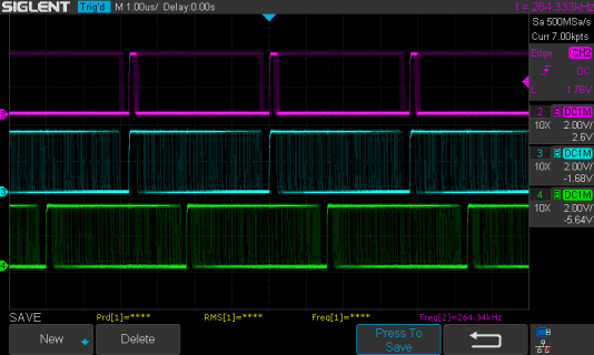
It runs the PWM at 264.6kHz (6 times audio rate) to make filtering easier (or for direct class D output).

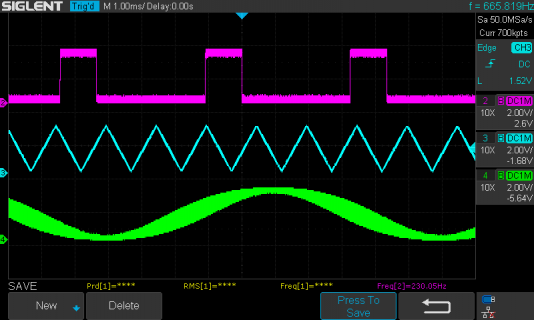
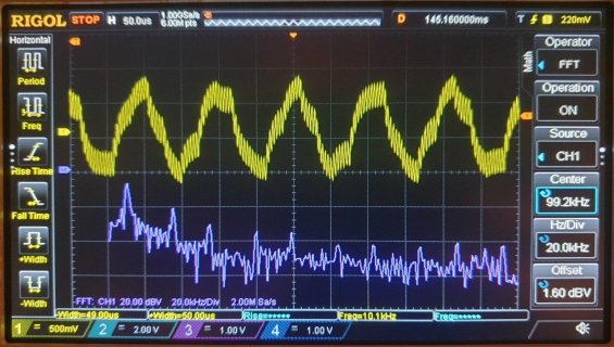
Still need to test if the clocking works against other audio input and outputs. Here's some 'scope shots with three separate instances
running from separate AudioSynthWaveform's. And the branch in my repo...

https://github.com/MarkTillotson/Audio/tree/noise_shaped_pwm

three_pwm.png
three_pwm_unfilt.png
 
Ok, found the mistake in code... It was simply due to a wrong Audioconnection. So, actually AudioOutputPWM works fine on T41 togheter with Audio Board and all other objects I'm using!
Now, my last wish is to solve the mysterious issue that afflicts my output filter !! ;)
 
Last edited:
I am also working on a noise-shaped PWM output class, which only needs one pin to output a quality signal (basically the same
sort of approach as the MQS but using any FlexPWM connected pin).

It runs the PWM at 264.6kHz (6 times audio rate) to make filtering easier (or for direct class D output).

Still need to test if the clocking works against other audio input and outputs. Here's some 'scope shots with three separate instances
running from separate AudioSynthWaveform's. And the branch in my repo...

https://github.com/MarkTillotson/Audio/tree/noise_shaped_pwm

View attachment 27734
View attachment 27735

I'm sorry that I ignore the use of this tool... But interesting that it includes a 1pin/hi-frequency PWM ... Maybe it could be used as "simple" PWM audio output?
 
Now I just loaded AudioOutputNoiseShapedPWM, and set:
begin (3) [ instead of begin(2) ]

in order to use the existing connection to the output filter... It works fine! (sorry, but I always feel surprised when software runs correctly!)
 
If you have issues with it let me know - you should be able to use up to 4 independent instances of it, so long as you don't use any
of the clashing pairs I've mentioned above (2,3) (6,9) (7,8) within that set of upto 4 instances.

I might have a go at generalizing it to use QuadTimer PWM pins too, but haven't looked at QuadTimer's yet.
 
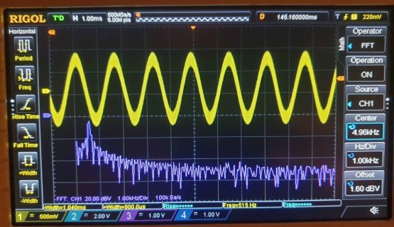
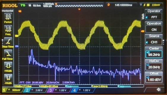
Set up 1 instance, on a naked T41; sweeping a sinus tone from 20Hz to 15KHz I just notice an increase of distorsion above 2KHz (maybe due to the filter? I should at least compare with the Audio Board's output.. ) that anyway is absolutely not critical for my application; I upload some shots:

515Hz
514.jpg

3890Hz
3890.jpg

10KHz
10K.jpg
 
Set up 1 instance, on a naked T41; sweeping a sinus tone from 20Hz to 15KHz I just notice an increase of distorsion above 2KHz (maybe due to the filter?

No, that's likely to be PWM distortion, made worse by the fact its not using phase-correct PWM (which I don't think can be fixed
as the DMA can only update one edge, not both). If only one edge moves the signal value is mixed into the time-domain causing
harmonic generation - this increases with signal frequency, signal amplitude, but decreases with PWM frequency (another reason
to raise the PWM frequency up to the 100's of kHz region)

Phase-correct PWM doesn't seem to have been thought about when the DMA interface to the FlexPWM units was designed, despite
it being almost always the best mode to do PWM in for any purpose. Ho hum...
 
Phase-correct PWM doesn't seem to have been thought about when the DMA interface to the FlexPWM units was designed, despite
it being almost always the best mode to do PWM in for any purpose. Ho hum...

This leads to the conclusion that ideally I should be using interrupts per pwm cycle (rather than per 128 sample block), in order to
have full control of the PWM hardware (allowing using those pin pairs, and phase-correct PWM. On the T4 there's enough processor
oomph to permit running an ISR every 5us or so if you want, but it won't scale well to multiple pins if running at high pwm frequencies.

Then I had another idea - to emulate analog class-D generation by curve-fitting interpolating polynomials to the waveform and computing
the precise clock cycle for each edge. Its something I recall I've modelled in Python a while back, I might review how well this performs
 
just for curiosity: if I don't mistake "normal" pwm pulses have a temporary fixed start point; we would prefer that the center of each pulse had a fixed position in time, so we modulate their phase to get a better distribution; but, doing this, don't we risk to overlap adiacent pulses?
 
Yes, its about having symmetrical pulses about stable clock intervals - don't worry about overlap, its scaled not to overlap.

One issue I've investigated is the relative clock rates when using both PWM and I2S - at no CPU frequency could I get them
to match up with the same 44.1kSPS, due I think to the different clocking/PLL arrangements for I2S and PWM.

This means running both in a sketch will cause the relative timing to drift until a whole block difference, then it will jump back
(discarding a block or inserting a block of silence).

This is not a simple thing to fix as the relative clock ratio needs to be known and then corrected for by interpolation.
 
I've updated the noise shaping code: https://github.com/MarkTillotson/Audio/tree/noise_shaped_pwm

It should now handle the case where I2S is driving updates at exactly 44100Hz yet the PWM is not quite accurate for this - using buffering
and interpolation. It currently doesn't work at 24MHz, since the PWM resolution is too low, but seems to be reasonable now, nominally doing
264.6kHz PWM. Same restriction to QuadPWM pins and same issue with pin pairs (2,3), (7,8), (6,9)
 
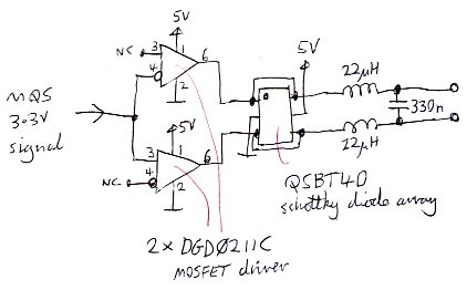
BTW I had a look for a cheap MOSFET driver chip that might serve as a power amplification for MQS or PWM, and found the DGD0211C, so here's my take on a speaker drive circuit from such an output:
MQS_circuit.jpg
The chip has both inverting and non-inverting logic inputs avoiding the need for an inverter to get anti-phase drive.
I haven't tested this (though I have used similar circuits in the past with MIC4422 drivers).

The output filter is assuming the MQS at 352.8kHz which seems to be the rate.

[ Note that the necessary decoupling caps aren't shown (10uF ceramic for each DGD0211C seems about right), and the quad Schottky array might be overkill - its there to prevent inductive kickback from the speaker coil ]
 
BTW I had a look for a cheap MOSFET driver chip that might serve as a power amplification for MQS or PWM, and found the DGD0211C, so here's my take on a speaker drive circuit from such an output:
View attachment 27792
The chip has both inverting and non-inverting logic inputs avoiding the need for an inverter to get anti-phase drive.
I haven't tested this (though I have used similar circuits in the past with MIC4422 drivers).

The output filter is assuming the MQS at 352.8kHz which seems to be the rate.

[ Note that the necessary decoupling caps aren't shown (10uF ceramic for each DGD0211C seems about right), and the quad Schottky array might be overkill - its there to prevent inductive kickback from the speaker coil ]

Hi Mark sorry for my late reply; it's a really nice schematics, I'll try to realize it :)
 
Back
Top