Teensy 4.1 - Damaged Pullup resistors (I think)

Ovidiu

Member
Hello everyone,

I was working on a menu interface using a rotary encoder (Enc A, Enc B, Push) and all was good until the Push button stopped working after about 2 days. I moved from Pin 30 to Pin 31 and it was all working fine, didn't put too much thought into it. Next day Enc A pin failed (pin 28).

After a quick look into the voltages with a scope I think I've damaged the PullUP resistors. Not sure how, but I did it.

Idle voltages on the idle pins are approx. 400mV (8bit oscilloscope). Working PINs have PullUp of 2.8V.

Initial test circuit (used for push button) might not be right, I've soldered the capacitor in the wrong location, but should still be ok.
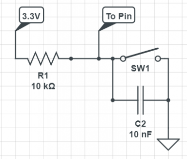
Wrong CapConnection used for Push.png
The second one should be ok (Enc A), but still damaged the pullup resistor. Are series resistors needed for using the pin pulled to GND?
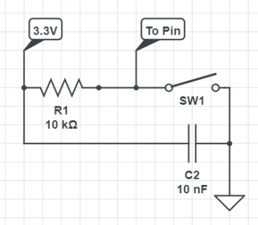
Should be ok CapConnection used for Enc A.pngShould be ok CapConnection used for Enc A.png

Code I use for test.

Code:
const byte interruptPin = 30;  // Pin 28 - Nok  Pin 29 - Ok  Pin 30 - Nok  Pin 31 - Ok   
volatile byte  numberofpressed=0;

void setup() {
  Serial.begin(9600);
  Serial.println("Basic Interrupt Test:");
  pinMode(interruptPin, INPUT_PULLUP);
  attachInterrupt(digitalPinToInterrupt(interruptPin), PressedButton, CHANGE);
}

void loop() {
      //Serial.println(numberofpressed);

}

void PressedButton() {
  numberofpressed ++;
  Serial.print (numberofpressed/2);   Serial.print ("  ");
  Serial.println (digitalRead (interruptPin));
}

Do you think the pullup's are damaged? How did I manage to do that?

Thank you!
 
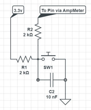
It looks like the PINs are out. Started another set of tests and using the internal pullup resistors. Started with the schematic below 10K resistors. Voltage on the PIN was reaching 2.3V (140uA pin current consumption with the button now pushed).

Decided to change the resistors to 2K (to up the voltage towards 3V) and it looked to be working for a bit (erratic, but working) and after couple of minutes the current consumption to the pin went up to 1mA pin voltage 600mV and any detection stopped.

Update test.png
 
Sampling of the pin still works, every time I plug in the wire to the pin (that being with the capacitor charged) the interrupt is detected.
 
Try losing the capacitor or reducing it to 1nF, it risks briefly back-feeding the pin when the power is removed - this is a possible mechanism for damage.

Rotary encoders shouldn't lose count if there's contact bounce due to the nature of quadrature signals

However I'm not convinced that's really the issue. Perhaps your grounding isn't solid - since the ground is routed
direct into the pin it had better be a good ground.

You may also have some large loops in your wiring acting as magnetic antennas, in which case you need some protection
on the pin (schottky diodes to the rails and series resistance).
 
Thanks Mark.

Didn't have any large loops in the wiring. Any tests I can do to check if the PINs are dead, or I am doing something stupid?
 
As a quick way to test, I tried this program on a Teensy 4.1.

Code:
const int pin = 30;

void setup() {
}

void loop() {
  pinMode(pin, INPUT_PULLUP);
  delay(2000);
  pinMode(pin, INPUT_PULLDOWN);
  delay(2000);
}

When I connect only my voltmeter between pin 30 and GND (but no other connections except the USB cable), it shows alternating between 0 and 3.29 volts.

Then I added a 47K resistor, also connected between pin 30 and GND (I just used clip leads to connect it right to the multimeter leads). With the resistor in place, I see the reading alternate between 0 to 2.18 volts.

Hopefully this helps with a simple way to test and the expected result you should see. But do keep in mind the resistor value inside the chip can vary quite a lot. I also used a 5% tolerance resistor. If you try this test and get a similar result that differs somewhat from 2.18V, know the exact voltage depends on the specific resistor values which can vary from chip to chip and also with temperature.

When I unclip the 47K resistor, the readings return to 0 and 3.29V.
 
*Healthy Pin 31* // *Damaged Pin 30*
PullUp: 3.27V // 128mV
PullDown: 0V // 0V
Output: 0V // 0mV

With added 30k resistor (didn't have a 47k but found 2x15K)

*Healthy Pin 31* // *Damaged Pin 30*
PullUp: 1.83V @61.4uA // 124mV @4.2uA
PullDown: 0V @0uA // 0V @0uA
Output: 0V @0uA // 0V @0uA

The strange thing is that Pin 28, that I am very sure it wasn't working yesterday, gives good results now. That until I try to use it as a interrupt pin, it's unstable.

I think it's quite safe to call the 2 pins (28&30) dead from an input point of view.

The only thing I am annoyed about is the fact that I've damaged 2 pins, but learnt nothing from it. I will try to recreate the damage using the initial components, this time with a pin I don't plan to use, pin 30 was allocated to CAN3, doh...


Code:
const int pin = 28;// Pin 28 - Nok  Pin 29 - Ok  Pin 30 - Nok  Pin 31 - Ok   


void setup() {
  Serial.begin(9600);
  Serial.println("Basic PIN Test:");
}

void loop() {
  pinMode(pin, INPUT_PULLUP);
  Serial.println("PullUp active");
  delay(5000);
  Serial.println("PullDown Active");
  pinMode(pin, INPUT_PULLDOWN);
  delay(5000);
  pinMode(pin, OUTPUT);
  Serial.println("Output Active");
  delay(5000);
}

Thank you for your help!
 
.... this time with a pin I don't plan to use, pin 30 was allocated to CAN3, doh...

Actually, just tested, PIN30 works just fine as CRX3. Can frames are working just fine on CAN3. Confusion reaches a new maximum :)) Does the CAN peripheral use it's own pin sampling unit?
 
Can you run this on the affected pins and watch with a voltmeter to check if GPIO output still works?

Code:
const int pin = 30;

void setup() {
  pinMode(pin, OUTPUT);
}

void loop() {
  digitalWrite(pin, HIGH);
  delay(2000);
  digitalWrite(pin, LOW);
  delay(2000);
}

EDIT: Please run this test with the resistor & voltmeter connected. Then while leaving all the wires in place, upload the code from msg #6. Without altering the wiring or doing anything else physically with the hardware, by only changing the software, can you go from reading 0 to 3.3V with this GPIO output test to the pullup & pulldown resistor (with external resistor) test.
 
Last edited:
Sure!

Connected:
Voltmeter to pin 30 and ground.
30K resistors between Pin30 and GND.

Flashed
Code:
const int pin = 30;

void setup() {
  pinMode(pin, OUTPUT);
}

void loop() {
  digitalWrite(pin, HIGH);
  delay(2000);
  digitalWrite(pin, LOW);
  delay(2000);
}

Pin High voltage - 3.08V
Pin Low voltage - 0V

Then without any hardware alterations, I've changed the code
Code:
const int pin = 30;

void setup() {
}

void loop() {
  pinMode(pin, INPUT_PULLUP);
  delay(2000);
  pinMode(pin, INPUT_PULLDOWN);
  delay(2000);
}

PullUp - 64mV
PullDown - 9mV

What are you thinking Paul?
 
My general thinking is ESD tends to be the Boogeyman of the electronics industry! It could have been ESD damage, but at least to me that's not a very satisfying explanation when the rest of the pin's functionality seems to work.

I reached out to someone at NXP. Understandably, ESD was their first thought. And realistically, this is a sample size of 1. I vaguely recall seeing at least 1 other thread a while ago reporting a similar issue, but can't find it right now. Maybe Defragster or other regulars here will recall it?

I definitely want to get this damaged Teensy. I've asked Robin to contact you to about sending a free replacement and arrange returning this damaged board. Just to be realistic, it'll probably sit here and collect dust until another case or two of this particular failure turn up.

Best I can say right now is this is quite mysterious. I'm not willing to just write it off and dismiss it as random ESD. But right now the most I can really do is get this board back here and wait & watch to any more similar cases. Wish I had a better & definitive answer, but right now I just don't know.
 
Ovidoi - I've sent you an email to the address you used to register with the forum.

-Robin
 
Hello both,

If there is a chance of getting an answer about what I've managed to do and 'obtain' this failure mode, sure!

Robin, I received the email, I will reply to it shortly.
 
...
I vaguely recall seeing at least 1 other thread a while ago reporting a similar issue, but can't find it right now. Maybe Defragster or other regulars here will recall it?
...

Vague at best here too. Too vague to get common word search to find anything either.

It certainly was not a trend I recall.

Noteworthy?: @MarkT's p#4 wonder on the 'none too small' CAP as attached, with personal non EE understanding beyond their nature of rushing to fill or empty given a path, or the number of electrons involved. Could that have stressed or hurt anything internal given the repeat make/break nature of the encoder?
 
Teensy on it's way. If you have some time after you receive it, please test it out. I'm curious about your findings.

Thanks!
 
Damaged board has been sent, and the new one received.

If you have some time to have a look, I would be curious to see your findings on the old board.

Thank you
 
I think I just had the same issue, or at least a very similar one. As Ovidiu, I'm using a set of rotary encoders, but in my case without any external pullup resistors, only using the INPUT_PULLUP. I have an exact same setup with a Teensy 3.2 board, and it works fine (I've been using it for several years now).

When I started testing the 4.1, everything worked at first, however soon the rotary encoder inputs stopped working, one after the other (I have 4 encoders in total). When I measure the voltages on the encoder inputs, they have between 200-700mV, the other ones are correct with 3.3V. Even the push button on the rotary encoder works.

I have the feeling that the rapid change caused by turning the rotary encoders somehow damage the internal pullup resistors or something.

I'm going to try to hook up external pullup resistors and configure to INPUT only to see if that works.
 
Just to confirm, with the external 10k pullup resistors and configuring the pins with INPUT instead of INPUT_PULLUP everything now works correctly.

@Robin should there be a warning somewhere that rotary encoders should ONLY be used with external pullup resistors?
 
Back
Top