MODBUS RTU communication

I have a TEENSY 4.0 and multiple angular transducers ( Modbus-RTU supported). From each Angular transducer I have to read 8 words and write 2 words. But writing is occasional because it is used for presetting, Offset ,direction change etc.
Can anyone please provide me proper guidance to communicate with the devices. I have following hardware with me.

1. Teensy 4.0

2. TTL to rs485 (MAX 485 interface module)

3. Angular Transducer with Modbus support

4. Power supply 5v dc

5. wires and bread board
 
Sir ,
Thank you very much for your prompt reply.
I am very much new to micro controllers. But I am conversant with programming like Structured Text.
What I want to know is how to implement this library(https://github.com/PaulStoffregen/ArduinoModbus) to read and write values to and from the Modbus supported device (which is a slave) which is connected to a TTL-RS485 interface board.
Regarding the TTL-RS485 interface board I have some doubts.
The board has two terminals . One has been marked as DI, DE, RE, RO and the other one marked as VCC, B, A, GND. I know the terminal marked as DI, DE, RE, RO is to be connected to Teensy side and the other one to Modbus device.
Can you please tell me which are the Teensy terminals that has to be connected to DI, DE, RE, RO and a sample code to control it while using ArduinoModbus library.
 
I am very much new to micro controllers. But I am conversant with programming like Structured Text.

The native language for Arduino (and Teensy) is C++, so you're going to have to learn a little bit of that before you can do something like use a library or create a program to communicate with an external Modbus device. Do you have the Arduino IDE and TeensyDuino installed?
 
The native language for Arduino (and Teensy) is C++, so you're going to have to learn a little bit of that before you can do something like use a library or create a program to communicate with an external Modbus device. Do you have the Arduino IDE and TeensyDuino installed?

Yes I have Arduino IDE and Teensyduino installed. Can you please guide me to implement this Library along with hardware connections?
 
Yes I have Arduino IDE and Teensyduino installed. Can you please guide me to implement this Library along with hardware connections?

Okay. As Paul said, you can use the ArduinoModbus library. To install it, open the Arduino IDE, go the Tools menu and choose Manage Libraries. When the Library Manager opens, wait for it to download the index, then type ArduinoModbus in the bar at the top. When you see the library in the main part of the window, click on the Install button. ArduinoModbus requires ArduinoRS485. I think it will ask you if you want to install that, too. If it does, say yes. If it does not ask you, search for ArduinoRS485 and install that, too. Once you have those installed, close the Library Manager, then go to the File menu of the Arduino IDE. Choose Examples, then navigate to the examples for ArduinoModbus and take a look at them.

If you look at the card that came with your Teensy 4.0, you'll see that hardware serial 1 (RX1, TX1) are on pins 0 and 1. You'll want to connect those two pins to the A and B pins of your TTL/485 converter. For the connections on the RS485 side, you'll have to review the documentation for the TTL/485 converter and for your Modbus device.

My advice is don't worry about the hardware connections for now. You still have a lot to learn about writing and testing very basic programs before you'll be able to write/run a program on Teensy to communicate with your Modbus device. Start working through Teensy tutorials and example programs. If you've never built a program with Arduino, start with Blink and change the blink rate. This forum is not a place to ask people to write your program for you. You have to work on it yourself and ask questions as you go.

Of course I will do that. I have already gone through many examples. But need to do more. I will try to write the code for my application and will post it here for suggestions.
once again thanking you.
 
If you look at the card that came with your Teensy 4.0, you'll see that hardware serial 1 (RX1, TX1) are on pins 0 and 1. You'll want to connect those two pins to the A and B pins of your TTL/485 converter.

This advice might not be quite right. You do need to use pin 0 (RX1) and pin 1 (TX1). But don't connect them to A & B on the MAX485 chip. The A & B pins are the RS485 signals which you connect to whatever modbus device(s) you wish to use.

When you use ArduinoModbus, it will require another library called ArduinoRS485. Get it here:

https://github.com/arduino-libraries/ArduinoRS485

I believe these are the default connections ArduinoRS485 expects:

MAX485 DI - Teensy pin 1 (TX)
MAX485 DE - Teensy pin 20 (A6)
MAX485 RE - Teensy pin 19 (A5)
MAX485 RO - Teensy pin 0 (RX) - but beware 5V, see next message

The specific pins ArduinoRS485 uses are controlled in 2 places. First is RS485.h starting at line 25.

https://github.com/arduino-librarie...39b4264527388f6d75df2e14d649f/src/RS485.h#L25

These lines control which pins it will use for DE & RE.

Code:
#ifdef __AVR__
#define RS485_DEFAULT_DE_PIN 2
#define RS485_DEFAULT_RE_PIN -1
#else[B]
[COLOR="#FF0000"]#define RS485_DEFAULT_DE_PIN A6
#define RS485_DEFAULT_RE_PIN A5[/COLOR][/B]
#endif

If you want to use different pins, I believe you can just edit RS485.h and change these to any digital pin. I believe setting RS485_DEFAULT_RE_PIN to -1 means it will only use DE. In that case, you could connect both DE and RE to that single pin on Teensy.

Which serial pins ArduinoRS485 uses is a little more complicated. That is controlled by the last line in RS485.cpp.

https://github.com/arduino-librarie...4264527388f6d75df2e14d649f/src/RS485.cpp#L189

This is the code:

Code:
RS485Class RS485([B][COLOR="#FF0000"]SERIAL_PORT_HARDWARE[/COLOR][/B], RS485_DEFAULT_TX_PIN, RS485_DEFAULT_DE_PIN, RS485_DEFAULT_RE_PIN);

The special name "SERIAL_PORT_HARDWARE" is actually defined in the core library, in pins_arduino.h.

https://github.com/PaulStoffregen/c...32763fe97e2a99e7e/teensy4/pins_arduino.h#L184

For Teensy, it is always this:

Code:
#define SERIAL_PORT_HARDWARE		[B][COLOR="#FF0000"]Serial1[/COLOR][/B]

If you wanted to use a different pins, you could just edit that last line in RS485.h. For example, if you wanted to use Serial4 (pins 16 & 17) and pin 18 for both DE+RE, I'm pretty sure you could just edit RS485.cpp like this:

Code:
RS485Class RS485(Serial4, 17, 18, -1);

But to use ArduinoModbus and ArduinoRS485 as-is, these would be the pins to connect between Teensy and MAX485.

MAX485 DI - Teensy pin 1 (TX)
MAX485 DE - Teensy pin 20 (A6)
MAX485 RE - Teensy pin 19 (A5)
MAX485 RO - Teensy pin 0 (RX) - but beware 5V, see next message

The MAX485 A & B pins are the actual RS-485 signals which you would connect to the Modbus RTU device you wish to use.
 
Last edited:
The other concern I would have is the MAX485 RO signal. If the MAX485 chip is powered by 5V, it will probably transmit a 5 volt signal on its RO pin.

Teensy pin 0 (RX1) is not 5 volt tolerant. A 5 volt output from MAX485 could damage your Teensy. Be careful!

With MAX485, you will probably need a level shifter or resistor divider between MAX485 RO and Teensy pin 0 (RX1) to reduce the 5 volt output to only 3.3V.

Another option would be to use a chip like MAX3485 which can be powered by 3.3V and will transmit a 3.3V signal on RO.

If you will buy another chip, you might also consider getting one of the chips with slew rate limiting. They only work up to 250000 baud, which is plenty fast enough for Modbus. The slew rate limit feature gives much better signal transmission if your RS485 cable does not have proper termination resistors on both sides, or if the resistors are mismatched to the type of cable you use.


Regarding the RO output, I would recommend connecting all the other signals and power first. Then use a voltmeter or oscilloscope to monitor the RO output signals BEFORE you connect it to Teensy. If the voltage is higher than 3.3V, do not connect to Teensy pin 0. Higher than 3.3V can cause damage to Teensy. Build and test the circuit to reduce RO voltage. Only connect it to Teensy pin 0 (RX1) when you are certain the voltage is safely within the allowed 0 to 3.3V range.
 
Thank you for your detailed reply. As per your advice I will prefer to get a different RS485 transceiver which will support 3.3 volts to prevent any damage to Teensy. So I am going to order that. Once I get it ,I will post results here. In between I will try the code and connection on my Arduino Nano.
 
Hi All
I am back.
Fortunately I got a system which has Teensy 3.2 as its controller. The system has one SPI Display also. The system is used to display the value(Angle) from the Modbus - RTU based Angular transducer. I tested the system and found that it is correctly displaying the value coming from Angular transducer. The system has also MAX3485 IC interface for Modbus connections. But I do not have the code of the Teensy 3.2 installed in the system.
So I tried a sample code(Modbus RTU Temperature Sensor) with a spare teensy 3.2 to get values from Angular transducer using Arduino Modbus library. But was unsuccessful. I am not interested about the LCD display part. But I think the code shall be able to display values on serial monitor. When I run the code, I am getting "failed to read registers! Connection timed out" on the serial monitor.

Before posting the sample code I may prefer to state here the connections between Teensy and MAX3485 IC.

1. MAX4385 is powered from 3.3 v supply from Teensy.
2. RE & DE pins of MAX3485 are shorted together and connected to 6th pin of Teensy.
3. RO & DI pins of MAX3485 are connected to Modbus device (here the Angular transducer).

Regarding Modbus device (https://www.usdigital.com/media/vxsibyx1/t7_modbus_communication_user_guide_2.pdf) it is inclinometer made by US Digital (https://www.usdigital.com/products/inclinometers/T7) and has serial configuration Add-12, 38400 baud, 8 data bits, even parity and 1 stop bit.

https://www.usdigital.com/products/inclinometers/T7

https://www.usdigital.com/media/vxsibyx1/t7_modbus_communication_user_guide_2.pdf

As earlier advised by Mr. PaulStoffregen I have changed the default PIN configuration to 6 in RS485.h as given below ,

#ifdef __AVR__
#define RS485_DEFAULT_DE_PIN 6
#define RS485_DEFAULT_RE_PIN -1
#else
#define RS485_DEFAULT_DE_PIN 6
#define RS485_DEFAULT_RE_PIN -1
#endif

Also I tested the voltage level of Teensy PIN-6 by changing pre delay and post delay to 500ms in the RS485.h
#define RS485_DEFAULT_PRE_DELAY 50
#define RS485_DEFAULT_POST_DELAY 50
And I found the DE&RE pin voltage level is rising to 3.3 volts and then back to zero.

Please find my sample code below. Kindly suggest the rectifications needed for establishing Modbus communication.

#include <ArduinoModbus.h>

float Ang1;
float Ang2;

void setup() {

Serial2.begin(38400,SERIAL_8E1);
while (!Serial2);

Serial.println("T7_Inclinometer");
// start the Modbus RTU client
if (!ModbusRTUClient.begin(38400)) {
Serial.println("Failed to start Modbus RTU Client!");
while (1);
}
}

void loop() {

// send a Holding registers read request to (slave) id 12, for 2 registers
if (!ModbusRTUClient.requestFrom(12, HOLDING_REGISTERS, 0x01, 2)) {
Serial.print("failed to read registers! ");
Serial.println(ModbusRTUClient.lastError());
} else {
// If the request succeeds, the sensor sends the readings, that are
// stored in the holding registers. The read() method can be used to
// get the raw temperature and the humidity values.
short rawAng1 = ModbusRTUClient.read();
short rawAng2 = ModbusRTUClient.read();

// To get the temperature in Celsius and the humidity reading as
// a percentage, divide the raw value by 10.0.
Ang1 = rawAng1 / 10.0;
Ang2 = rawAng2 / 10.0;
Serial.println(Ang1);
Serial.println(Ang2);
}

delay(5000);
}
 

Attachments

  • t7_modbus_communication_user_guide_2.pdf
    738.2 KB · Views: 190
3. RO & DI pins of MAX3485 are connected to Modbus device (here the Angular transducer).

That's not right.

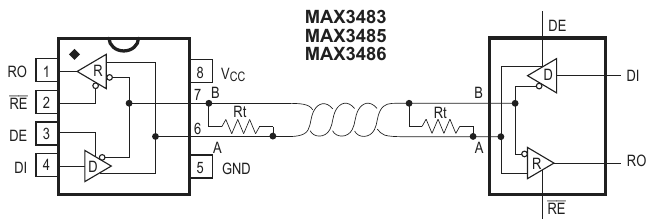
The MAX3485 RO & DI pins are supposed to connect to Teensy. You need to connect MAX3485 pins A & B to the Modbus device.

Maybe this diagram from page 8 of the MAX3485 datasheet can help?

screenshot.png

Also see the connections I suggested in msg #8.

I see your program has Serial2.begin(). If you connect R0 & DI to Teensy 3.2 pins 9 & 10, you also need to understand that just using Serial2.begin() in your program will NOT cause ArduinoModbus & ArduinoRS485 to use Serial2. It will still default to Serial1. To use a different port, you need to edit the last line in RS485.cpp, as I described also in msg #8.
 
Also for 8E1 format, know the Serial2.begin() in your program will have no effect.

Even if you edit the last line of RS485.cpp so Serial2 is used, the actual communication settings used will depend on 1 of the 4 begin() functions inside RS485.cpp, on lines #31, #36, #41, or #46. When this code runs, it will reconfigure the serial port and the 8E2 setting you configured before starting the ArduinoModbus library will be overwritten.
 
One final tip for today... When editing Arduino libraries, a common pitfall is having 2 or more copies on your computer where you're making changes to a different copy that Arduino is actually using. It's really easy to waste an incredible amount of time where nothing you try makes any difference. Also really easy to check. When you start editing any library, I would recommend first adding an intentional syntax error and click Verify. If Arduino still compiles it successfully, you just saved yourself a lot of wasted time! Getting an error with line number on or near your intentional error confirms you're really editing the correct file.
 
Extremely sorry for incorrect posting of connection Max3485 to Teensy . RO and DI are connected to teensy and AB is connected to Modbus device.
I changed change 8N1 to 8E1 in RS485.cpp, on lines #31 #36 and again upload to Teensy. But still the same message
"failed to read registers! Connection timed out
failed to read registers! Connection timed out"
is showing on the serial monitor. Please advice
 
I tested as per your advice. I added one line in each file (RS485.cpp and RS485.h). The I verified the code. Both time verification failed and pointed towards wrong line added.
 
Please advice

I'm afraid I've already suggested every issue I am able to see based on the info you have provided. Maybe someone else might see something I have missed? But I just can't tell what may be wrong, other than the many issues I've already pointed out.

If you have access to an oscilloscope or logic analyzer, this would be the time to connect it to DI, DE, RO (and A & B if you can) and show the actual signals.
 
Ideally a scope or logic analyzer would show the 3 signals connected between Teensy and the MAX3485 chip. If we see only 1, that's better than none at all. But keep in mind the reality of this situation. You're asking people on the internet to help figure out why your electronics project isn't working. But we can't see the wires unless you show photos, we can't see the signals unless you connect equipment and show us, and everything we know of what you're actually seeing & experiencing is only from the words & images you post here.

Between connecting custom hardware, editing library source code, and running a program which may or may not be correct, there are a LOT of possible ways for something to go wrong. Correctly diagnosing this sort of problem over the internet is very difficult. The more clearly you show us what you're really doing (eg, photos, screenshots, exact code used, clear descriptions of what your eyes really observe) the less blind guesswork is involved in trying to help.
 
MODBUS RTU is pretty simple. Unless you are trying to reuse code written by someone else for different hardware. Then you will have to dig into that code to see if it is doing what you need it to. Is it using the serial port you expect? Is the driver enable working? With the correct timing? (Waiting to turn it off after data has finished shifting out can be tricky.)

A logic probe will get you most of the way. Use it to verify that the driver enable to the MAX3485 is working and that serial data appears where you expect it. Don't forget to put a pullup on the serial data in as the MAX chips tristate the receiver output when disabled and a floating input will cause trouble.
 
Hi,

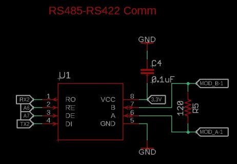
I am trying to establish MODBUS RTU connection with MASTER PLC using Micromod Teensy, but I was not successful. I want to make a connection via Serial2. I changed the RS485.h and RS485.cpp files as follows.

#define RS485_DEFAULT_TX_PIN 17
#define RS485_DEFAULT_DE_PIN A7
#define RS485_DEFAULT_RE_PIN A6

RS485Class RS485(SERIAL_PORT_HARDWARE1, RS485_DEFAULT_TX_PIN, RS485_DEFAULT_DE_PIN, RS485_DEFAULT_RE_PIN);

I have stated the scheme I used below.

schema.jpg

In the scenario, the master device needs to read a series of data from the teensy. Can you share me a sample code? I couldn't understand the examples found in this library. I get the "Invalid CRC" error in all my attempts.
 
Last edited:
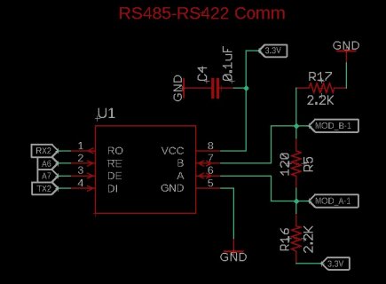
Hello,
Finally I solved the problem. The "milesg" approaches in the link below helped me solve the problem. In the MAX485 or MAX3485 IC, it is necessary to make output A pullup and output B pulldown. During the testing phase, 1k resistor was enough for me. (2.2k in design) I connected a 120 ohm resistor between A and B as stated on the information page. I made this communication via Micromod Teensy and used "Serial2". Here I used pins 21 for DE and 20 for RE. I also used pins 17 for TX2 and 16 for RX2. However, I could not transfer data at speeds above 57600 baud. It is necessary to make the first attempts with 9600 baud. The circuit I designed would work as a slave on Modbus and communicate with the CM1241 module on a SIEMENS 1200 series PLC. On the CM1241 module, I connected pin 3 to output A and pin 8 to output B.
On the software side, I used the "ModbusRTUSlave by C.M. Bulliner" library and was successful.

The pin numbers I mentioned above belong to Micromod Teensy. Pin numbers for other Teensy cards will vary.

https://forum.pjrc.com/threads/7084...or-Teensy4-1-running-Paul-s-ModbusRTU-library

schema.jpg
 
Last edited:
Back
Top