what do you do when you need more 3v3 juice?

neroroxxx

Well-known member
So i have a project that will have 8 to 24 74HC595s, I've tested 8 of them together using 4k7 resistors + PWM on the OE pin of the 595s to lower their brightness to prevent drawing too much current from the 3v3 regulator on the teensy, however i would like to increase the brightness significantly and i'm afraid that as i add more 595s and increase the brightness by lowering the resistor values for led's and removing the PWM i'll reach the recommended 250mA cap of the built in 3v3 regulator of the Teensy.

So basically i'm wondering if it's a safe/common practice to add an additional 3v3 regulator to step down the 5v power supply. Then using the external 3v3 supply to power the 595s while leaving the internal regulator on the teensy alone.

Aside from the obvious (sharing the ground and NOT joining the external and internal regulator's output) would there be any issues since the VCC of the 595s would be supplied by an external 3v3 regulator and the logic from the teensy's internal regulator?

BTW I'm using a 4.0 for this project.
 
I think I get what you are asking.

I always use buck converters to drop some DC source (anywhere from 9v to 24v) to 3V3 and feed that regulated supply in to the 3V3 pin on the Teensy. That same power supply feeds all my other gadgets (display, SD cards, buttons, led's, etc.). I actually never fed power into to the Vin pin even though there is an onboard regulator.

Hope this helps.
 
thank you for the reply! I read somewhere a post from Paul that the Teensy 4 is not designed to be powered via the 3v3 pins, I always have a 9V supply into an AMS117 or 7805 into VIN.
 
AP1117-3.3 - a commonly available low-dropout regulator that will source 0.8A and can derive 3.3V direct from 5V.

I always have a 9V supply into an AMS117 or 7805 into VIN.
AMS1117 perhaps? Same chip, different source. Also LM1117
 
From 9V to 3.3V a buck-converter is the obvious choice. Especially if this is all digital, as you'll get nearly 3 times the efficiency.
 
Is that a safe practice tho?

Using a 3.3v reg to provide VCC to all my sensors while the teensys internal 3.3v provides the VCC for the teensys logic?
 
Good point - perhaps slaving the sensor supply from the processor supply using a regulator with an enable pin driven from a comparator?
 
Note, if you are powering the Teensy with USB power, and drawing the power off the VIN pin, there is a fuse (*) between the USB power and the VIN pin that limits you to roughly 5 volts at 500 mA. I would imagine that if you need more power, you might need to draw the power off of the USB line before it is plugged into the Teensy (**). For the modern Teensies, the 3.3v regulator is on the order of 3.3 volts at 250 mA, so you do get more power by using the VIN pin

* When Paul has described this in the past, he said that it wasn't technically a fuse, but it acted as one, and the 500 mA is not a hard limit, but the recommended value (the Teensy does start getting toasty if you get more). However, since I'm a software guy, I didn't pick up on the fine details. But as a rule of thumb, you should not expect to draw more than 500 mA from the VIN pin (roughly 2.5 watts from VIN vs. 0.825 watts from 3.3v).

** The USB 2.0 standard says that 500 mA is the minimum limit for power. USB sources can provide more, but you aren't guaranteed to get it. A lot of the 'smart' USB devices will not give you more than 500 mA unless the device uses known profiles to ask for higher amps (such as 2.1 amps used for charging). The Teensy does not signal it is a device that can handle more than 500 mA.
 
Last edited:
From 12V, I sometimes I make 5V and 3v3 using 1A switching regulators, the 3v3 for powering other devices, which connect to T4 via logic gpio. Be sure to tie grounds together. Don't connect the 2 different 3v3 rails. Add 10k series resistors to each T4 gpio to those devices for good practice. Not usually necessary.
 
Question about your powering issue solution

Note, if you are powering the Teensy with USB power, and drawing the power off the VIN pin, there is a fuse (*) between the USB power and the VIN pin that limits you to roughly 5 volts at 500 mA. I would imagine that if you need more power, you might need to draw the power off of the USB line before it is plugged into the Teensy (**). For the modern Teensies, the 3.3v regulator is on the order of 3.3 volts at 250 mA, so you do get more power by using the VIN pin

* When Paul has described this in the past, he said that it wasn't technically a fuse, but it acted as one, and the 500 mA is not a hard limit, but the recommended value (the Teensy does start getting toasty if you get more). However, since I'm a software guy, I didn't pick up on the fine details. But as a rule of thumb, you should not expect to draw more than 500 mA from the VIN pin (roughly 2.5 watts from VIN vs. 0.825 watts from 3.3v).

** The USB 2.0 standard says that 500 mA is the minimum limit for power. USB sources can provide more, but you aren't guaranteed to get it. A lot of the 'smart' USB devices will not give you more than 500 mA unless the device uses known profiles to ask for higher amps (such as 2.1 amps used for charging). The Teensy does not signal it is a device that can handle more than 500 mA.


Hey there @MichaelMeissner and hello Teensy community, this is my first post.

Sir, Your reply has my attention, as I am building a new Guitar peddleboard using a Teensy 4.1 and I may encounter some powering issues using the Teensy.
My existing DIY peddleboard is build using an Arduino Due and works perfectly, but the T4.1 is 24.3 times faster in processing speed than the Due (theoreticly).

The possible powering issue:
The arduino Due has a 500ma output on the 3.3V and the T4.1 has 250ma. My peddleboard uses 15 tft screens that take 30ma each, so the Teensy is comming short.
I am powering the peddleboard using a 5V usb powerbank. This goes directly into the microUSB input of the teensy.

What is my question about your post:
You state that the 5V has 500ma output. My question would be. Does this create an option for me to have a regulator from the 5V (VIN) to 3.3V and then power the screens and use the Teensy GND?
Or do you think that the second option "might need to draw the power off of the USB line before it is plugged into the Teensy (**)" would be better for my project.


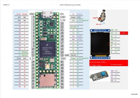
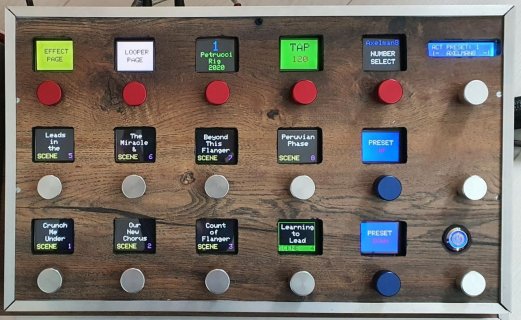
Here is some info about my project and how the switches and screens are connected on the Teensy.
Hope you can help me out, as I have no clue what is best NOT to fry the teensy.

Cheers


Teensy_setup.jpg

Controller_1.jpg
 
Hey there @MichaelMeissner and hello Teensy community, this is my first post.

Sir, Your reply has my attention, as I am building a new Guitar peddleboard using a Teensy 4.1 and I may encounter some powering issues using the Teensy.
My existing DIY peddleboard is build using an Arduino Due and works perfectly, but the T4.1 is 24.3 times faster in processing speed than the Due (theoreticly).

The possible powering issue:
The arduino Due has a 500ma output on the 3.3V and the T4.1 has 250ma. My peddleboard uses 15 tft screens that take 30ma each, so the Teensy is comming short.
I am powering the peddleboard using a 5V usb powerbank. This goes directly into the microUSB input of the teensy.

What is my question about your post:
You state that the 5V has 500ma output. My question would be. Does this create an option for me to have a regulator from the 5V (VIN) to 3.3V and then power the screens and use the Teensy GND?
Or do you think that the second option "might need to draw the power off of the USB line before it is plugged into the Teensy (**)" would be better for my project.


Here is some info about my project and how the switches and screens are connected on the Teensy.
Hope you can help me out, as I have no clue what is best NOT to fry the teensy.

Cheers
In general let me say, I am a software guy, not an IEEE engineer, so assume all of my answers are as I grok things (and having been part of this community since the original Teensy 3.0), and not with deep understanding :D

That is a lot of screens, so I might imagine you might need to be careful with power. A Teensy 4.1 draws about 120mA from a 5v USB circuit, so you roughly have 380mA to draw from the VIN pin to power other devices. You can draw somewhat more, but 500mA is what it is designed for.

There are a couple of ways to proceed:
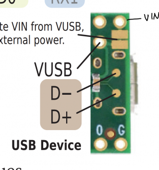
  • If you look on the back of the pinout card (https://www.pjrc.com/teensy/pinout.html), At the bottom right hand side, shows two solder pads and the inner pin which is next to the ground pin between 3.3v and VIN. This pin is 'VUSB' which is the power from the USB device, and the solder pads normally connect VIN and VUSB. If you use a knife like an Exacto (tm) knife, you can cut the solder trace between these. Then you connect VIN and Ground to your 5v power source. The USB cable that is used to program the Teensy and allow for USB tracing will not power the Teensy. Instead,you must power the Teensy though the VIN pin.
  • Alternatively, assuming those are I2C screens, you could apply power to the i2c bus from a 5v source, and just connect the ground wire between the Teensy and the i2c devices. The USB would power the Teensy directly, but not power the screens.
  • Or you can make a custom USB cable that has a USB A female plug on one side, the USB micro-B plug on the other, and then connect the 5v and ground wires to a separate 3.3v regulator which goes to power the screens. To the end that connects to the Teensy, provide the ground but not 5v power, and then connect the 5v power to VIN.
 
You can power off the micro-USB, which should be rated to 1A @ 5V (the connector is rated for 1A, make sure your cable and power source are also 1A rated). Otherwise, USB with data is typically limited to 500mA.

For 15 x .030mA displays, that's going to be 450mA. The Teensy will draw ~120mA. You are pulling 570mA, and add any other chips, LED, devices that you are connecting to. Keep it under 1A to be safe.

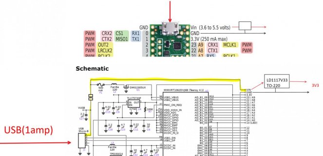
Connect regulator to the Vin, which will provide 5V from the USB connector.

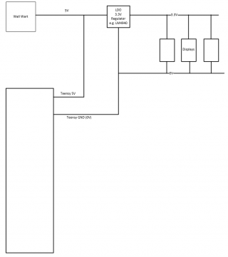
The LDO will be dropping from 5V to 3.3, so the heat generated will be (5V-3.3V) * .45A = .765W. This needs some consideration, I would highly recommend a TO-220 package LDO with some thermal coupling to dissipate the heat (heat sink, PCB, housing, etc). If the TO-220 is just sitting in the air, it will get hot, but probably won't burn up.

A switching regulator would be better, more efficient, for example a 90% efficient switching regulator will draw about .33A@5V to make .45A@3.3V, which would keep you under the 500mA USB limit. That would be my preference.

Here's a bit of a sketch, notice the highlighted path the 450mA will be taking. The Teensy will also take 5V, it has a fuse and is somewhat self-protected.
LDO.jpg

Note: the VUSB pin is also an option, it is that inner pin next to the GND pin. Might be a better option if you don't mind soldering to that pin.
vin.PNG
 
Last edited:
Hey there gents,

Thank you for the fast reply's @MichaelMeissner, @BriComp and @TeensyWolf
All the options together give me a very good options...

I will first try the option with the regulator as given by TeensyWolf. I got some heatsink's on top of the processor, but regulating is the best thing I can add to protect the Teensy.


As soon as i have a working solution I will report back here.


Cheers
 
Sorry I know I am late to the table... But I thought I would mention, that on some of my boards, I have used some simple step down VRs by Pololu.
They are actually DC/DC converters. https://www.pololu.com/category/131/step-down-voltage-regulators

Which one I would use depends on things like how much current. For example
.5 amp - https://www.pololu.com/product/2842
1 amp - https://www.pololu.com/product/2830

Nice thing about them are they handle pretty good voltage range, are self contained and you simply need to hook up, VIN/GND/VOUT...

Good luck


Hey there,

Thank you for the reply. That Volt regulator is inpressive. Now that i know how to bypass the screens to power them I am sure that a regulator is what i need.


Cheers
 
I would suggest something like in the picture below.
View attachment 27868

Thank you for the graph! so basically this is what i intend to do, all my designs use a USB Type B because they are sturdy, the power line from the USB jack goes to a Pair of diodes to switch between a dc power supply (9v to 5v) then into VIN, so i always power my teensy's directly into to VIN.

My question is if it's a safe or common to let the teensy use it's internal 3.3v regulator power the teensy and also the logic lines while an additional 3.3v supply will power the vcc of external displays, muxes, etc.

in other words, if the SDA and SCL from the teensy use the internal regulator while the vcc going to a sensor/display will be powered by an addon 3.3v regulator, would this cause any issues within the data?

I'm going to have to give it a shot i just would hate to burn a teensy 4 experimenting lol
 
The only potential problem would be if the displays were powered up and sending data to Teensy before the Teensy 3.3V was established.
If this is a concern then you could use a 3.3V regulator which has a power enable pin and supply this pin from the Teensy 3.3V pin.
In this way your displays etc would be powered after the Teensy has received power.
 
Back
Top