Different interrupt results between 4.1 and 4.0

Cr2O7

Member
Hi!

I am currently working on project aiming at connecting fuel meters, etc to the NMEA2000-network in my boat.
A part of the work is to create a simulators for the used devices. My first task is to emulate the flow meters.
They transmit pulses of which is proportional to the volume of fuel passed. The boat is equipped with two diesel engines, so four meters are needed.

In my development environment I've got one Teensy 4.1, running the target application and one Teensy 4.0 used
as an emulator for the real world devices. My concern here is the emulation of the flow meters. I am creating pulses
by using the PWM-functionality on the Teensy 4.0. When these pulses are sent to the Teensy 4.1 of the development environment everything is working as expected.

However, when a activate the target environment which is a Teensy 4.0 the pulse rates are different from the Teensy 4.1 and varies with time.

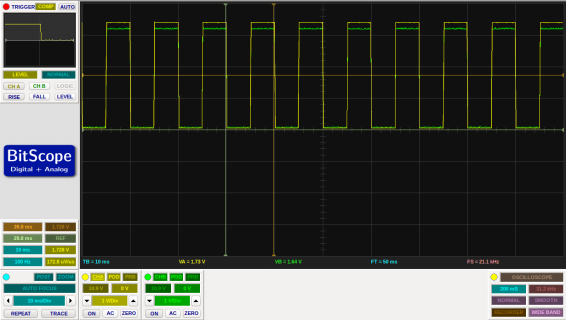
Please compare the outputs recorded in the files: PulsesTrace_from_Teensy4.0 and PulsesTrace_from_Teensy4.1.

The set PWM-frequencies are: 100, 80, 120 and 100Hz. This is seen in the output from the Teensy 4.1, but twice as
large due to the parameter CHANGE in the 'attachInterrupt'-function.

In the real world the flowmeters are driven by 12V, so therefore I let the generated pulses from the Teensy 4.0 pass
a logical voltage shifter to get the signal up to 12V. At the other end the opposite is done to get it back to 3.3V.

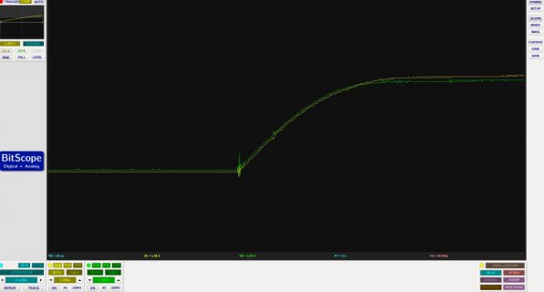
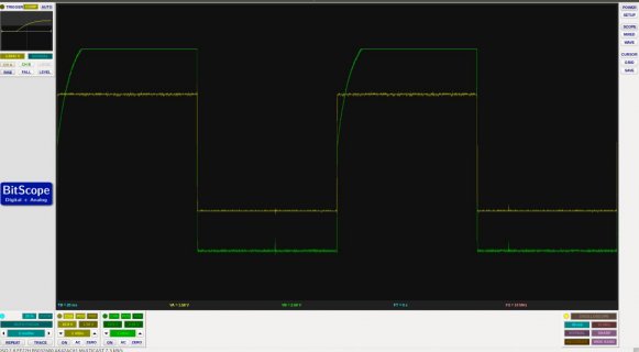
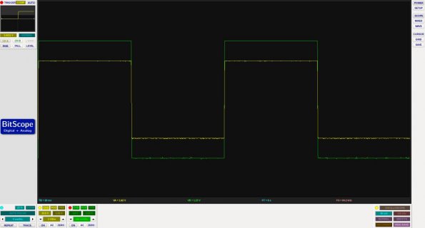
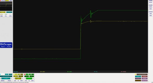
Furthermore, I measuring the pulses with a scope as they leave the emulator Teensy 4.0 and when arriving at the target Teensy 4.0 (3.3V side).

As can be seen in the output from the scope (Screenshot from 2022-03-22 11-50-22.png) these two frequencies are the same, 100Hz. The green colour are at the target side and the yellow at the emulator side.

Another difference is that the Teensy 4.0 uses an external SD-card reader, but on the Teensy 4.1 the builtin ditto is used.

I've provide some code related to the pulse counting instead of providing the complete code, which probably would be
too heavy to digest.

Finally, I have no idea what additional information may be of interest in order to pin this problem down.
Any responder please let me know and I'll supply it ASAP.

Code:
// Used pins.
#define PrimaryBBFlowmeterPin 2
#define ReturnBBFlowmeterPin  3
#define PrimarySBFlowmeterPin 5
#define ReturnSBFlowmeterPin  6
#define DS18B20Pin            4


// Definition of the struct holding the parameters for a fuel stream.
typedef struct FuelStreamCtrl
{
	
  void               (*PulseCntrFunc)(void);	  <---- Called interrupt function.
  int volatile       PulseCount;
  int                PulseCntPin;
  unsigned long long DS18B20Id;
  unsigned long      PreviousMillis;
  double             NozzleDiameter,
                     FlowInStream,
                     PulseRate,
                     Temperature,                    
                     ElapsedTime;

		
}FuelStreamCtrl_t;


// Interrupt functions one for each fuel stream.

void ReadBBFlowMeterPrimary(void)
{
	cli();
  FuelStream[PrimaryBB].PulseCount++;
  sei();
}

void ReadBBFlowMeterReturn(void)
{
	   cli();
     FuelStream[ReturnBB].PulseCount++;
     sei();  
}

void ReadSBFlowMeterPrimary(void)
{
	cli();
  FuelStream[PrimarySB].PulseCount++;
  sei();  
}

void ReadSBFlowMeterReturn(void)
{
	cli();
  FuelStream[ReturnSB].PulseCount++;
  sei();      
}


  // +++++++++ Define the flow stream parameters +++++++++. 
  FuelStream[PrimaryBB].PulseCntrFunc          = ReadBBFlowMeterPrimary;
  FuelStream[PrimaryBB].DS18B20Id              = PrimaryBBDS18x20SensorId;
  FuelStream[PrimaryBB].PulseCntPin            = PrimaryBBFlowmeterPin;
  FuelStream[PrimaryBB].NozzleDiameter         = NozzleDiameter[CurrentlyUsedNozzle];
  FuelStream[PrimaryBB].PreviousMillis         = millis();
  
  FuelStream[ReturnBB].PulseCntrFunc           = ReadBBFlowMeterReturn;
  FuelStream[ReturnBB].DS18B20Id               = ReturnBBDS18x20SensorId; 
  FuelStream[ReturnBB].PulseCntPin             = ReturnBBFlowmeterPin;
  FuelStream[ReturnBB].NozzleDiameter          = NozzleDiameter[CurrentlyUsedNozzle];
  FuelStream[ReturnBB].PreviousMillis          = millis();  

  FuelStream[PrimarySB].PulseCntrFunc          = ReadSBFlowMeterPrimary;
  FuelStream[PrimarySB].DS18B20Id              = PrimarySBDS18x20SensorId;
  FuelStream[PrimarySB].PulseCntPin            = PrimarySBFlowmeterPin;
  FuelStream[PrimarySB].NozzleDiameter         = NozzleDiameter[CurrentlyUsedNozzle];
  FuelStream[PrimarySB].PreviousMillis         = millis();      
  
  FuelStream[ReturnSB].PulseCntrFunc           = ReadSBFlowMeterReturn;
  FuelStream[ReturnSB].DS18B20Id               = ReturnSBDS18x20SensorId;
  FuelStream[ReturnSB].PulseCntPin             = ReturnSBFlowmeterPin;
  FuelStream[ReturnSB].NozzleDiameter          = NozzleDiameter[CurrentlyUsedNozzle];
  FuelStream[ReturnSB].PreviousMillis          = millis(); 
  
  
void SetUpPinIrpts(void)
{
	
  FuelStreamIdx_t	Idx = FirstFuelStreamIdx;          
  
  while(Idx < NbrOfFuelStreams)
  {
  	// Set the digital pin as input.
    pinMode(FuelStream[Idx].PulseCntPin, INPUT_PULLUP); 
    
    delayMicroseconds(100);
    
    // Define the function to handle the interrupt.
    attachInterrupt(FuelStream[Idx].PulseCntPin, FuelStream[Idx].PulseCntrFunc, CHANGE);   	
  	
  	Idx = FuelStreamIdx_t (Idx + 1);
  	
  }
  
}

Rgds,
Göran
 

Attachments

  • PulsesTrace_from_Teensy4.0.txt
    6.1 KB · Views: 38
  • PulsesTrace_from_Teensy4.1.txt
    3.1 KB · Views: 29
  • Screenshot from 2022-03-22 11-50-22.png
    Screenshot from 2022-03-22 11-50-22.png
    66 KB · Views: 44
Not really sure what is your question. The files you posted are ".txt", not images. Can you post something that shows the problem?
 
Not really sure what is your question. The files you posted are ".txt", not images. Can you post something that shows the problem?

same.

100Hz isn't fast enough to cause speed issues with simple counters, even with 4 of them overlapping
The PulseCount vars are properly volatile, but not seeing how they are read?
Writing them from loop could cause issues, seems if made uint32_t and left free running and just using the DIFF between readings.

Not sure why the added CLI and SEI - interrupts at same priority won't interfere?
That code is SHORT - so the _isr's may be hitting double without adding "DSB" ?: asm volatile ("dsb");

Does changing all to this help?
Code:
void ReadSBFlowMeterPrimary(void)
{
//   cli();
        FuelStream[PrimarySB].PulseCount++;
//   sei();  
      [B]asm volatile ("dsb");[/B]
}

And edit the PulseCount int's to uint32_t's
And when read, read current count and diff to prior { NEW - OLD } for the change count, then save the NEW as OLD for each. Do not write them to zero.
 
Hi again!

I'll try to explain my problem in more detail, but in short the generated frequencies are not properly read.
In this post you'll find a refined version of the code I am using for pulse generating and pulse counting.

The hardware used consists of three level shifters labelled: LevelShifter#1, LevelShifter#2 and LevelShifter#3.
These can be found here: https://www.pololu.com/product/2595/specs.
Three Teensy 4.0 are also utilised, labelled "Pulse reader" "Pulse generator" and "Target application".

The hardware are configured in two ways: "Set-up#1 and "Set-up#2, given in wiring.pdf.

The high voltage of the level shifters are 12V and the corresponding low ditto 3.3V.

The following frequencies are generated:
Pin 2: 100 Hz
Pin 3: 80 Hz
Pin 5: 120 Hz
Pin 6: 100 Hz

The output files corresponds to the wiring as follows:

Good_trace_all_pins_12V.txt Set-up#1
Bad_trace_12V_all_pins.txt Set-up#2
Good_trace_pin#3_12V.txt Set-up#2
Bad_trace_pin#2_and_pin#3_12V.txt Set-up#2

Please note that these are CSV-files in disguise, so for better readability, please open them with a suitable
spreadsheet application.

All the above mentioned files are also collected in file PulseTraces.txt, just change the extension to .ods and open it.

Observations
The pulses from all four pins are are successfully counted in "Set-up#1, in "Set-up#2 the frequency is correct only if
one pin is pulsed, two or more is unsuccessful.

The pulses on a scope looks fine, see my previous post.

I hope this documentation of the problem is better.

Rgds,
Göran

Pulses are generated as follows:

Code:
#ifndef _PULSEGENERATOR_H
#define _PULSEGENERATOR_H


#define CounterPinOne 											1
#define CounterPinTwo  											3
#define CounterPinThree 										5
#define CounterPinFour											6 

// Pulse frequency
#define FrequencyPinOne                     100  // Hz   
#define FrequencyPinTwo                     80   // Hz    
#define FrequencyPinThree                   120  // Hz    
#define FrequencyPinFour                    100  // Hz    

#define DutyCycle                           128  // 50%

#define NbrOfPins                           4

int Pin[NbrOfPins]       = { CounterPinOne , CounterPinTwo, CounterPinThree, CounterPinFour },
    Frequency[NbrOfPins] = {FrequencyPinOne, FrequencyPinTwo, FrequencyPinThree, FrequencyPinFour};


#endif


Code:
#include "PulseGenerator.h"

void setup() 
{
	
 int PinIdx = 0;  

  while(PinIdx < NbrOfPins)
  {
    analogWriteFrequency(Pin[PinIdx], Frequency[PinIdx]);
    analogWrite(Pin[PinIdx], DutyCycle); 
       
    PinIdx++;
  }      
	
}

void loop() 
{
	
}


Pulses read by:

Code:
#include <TeensyThreads.h>

#ifndef _PULSECOUNTTEST_H
#define _PULSECOUNTTEST_H

#define CounterOnePin 		2
#define CounterTwoPin 		3
#define CounterThreePin 	5
#define CounterFourPin 		6

#define ThreadFailed            						-1
#define CounterSamplingTime                 5000             // ms
#define StackSize1024                       1024
#define MaxTicks                            4294967295   // + 1 -> 0

typedef enum IrptCounterIdx
{
	  FirstCounter, SecondCounter, ThirdCounter, FourthCounter, NbrOfCounters
	  
}IrptCounterIdx_t;


typedef enum 
{
	
	SamplingThread,  NbrOfThreads
	
}ThreadIdx_t;

typedef struct InterruptCtrl
{
	
  unsigned long volatile PulseCount,
                         PreviousCount;
                         
  unsigned long          PreviousMillis,
                         ElapsedTime;

		
}InterruptCtrl_t;


typedef struct ThreadsDef
{
	
	ThreadFunctionNone Tread_F;
	char *ThreadName;
	int  ThreadID,
	     DelayThread,
	     StackSize;

}ThreadsDef_t;


void ReadCounterOne(void);
void ReadCounterTwo(void);
void ReadCounterThree(void);
void ReadCounterFour(void);
void GetCounters(void);
void Initialise(void);
void AddMyThread(ThreadsDef_t Thread);
void SetUpPinIrpts(void);
unsigned long GetElapsedTime(unsigned long BeginTime, unsigned long EndTime);


static int IrptPin[NbrOfCounters] = {CounterOnePin, CounterTwoPin,CounterThreePin, CounterFourPin};

ThreadFunctionNone IrptFunc[NbrOfCounters] = {ReadCounterOne, ReadCounterTwo, ReadCounterThree, ReadCounterFour};

#endif

Code:
#include "PulseCountTest.h"

InterruptCtrl_t IrtpCtrl[NbrOfCounters];


ThreadsDef_t MyThread[NbrOfThreads];

bool TraceFlag = true,
     Forever   = true;

void setup() 
{
  if(TraceFlag)
  {
    Serial.begin(115200);
    while(!Serial)
       delay(10);

    Serial.println("Buuu"); 
  }
  
  Initialise();

}

void loop() 
{
  // put your main code here, to run repeatedly:

}

//########################################
void ReadCounterOne(void)
{
	cli();
  IrtpCtrl[FirstCounter].PulseCount++;
  sei(); 
  asm volatile ("dsb");   
}

//########################################
void ReadCounterTwo(void)
{
	cli();
  IrtpCtrl[SecondCounter].PulseCount++;
  sei(); 
  asm volatile ("dsb");   
}

//########################################
void ReadCounterThree(void)
{
	cli();
  IrtpCtrl[ThirdCounter].PulseCount++;
  sei(); 
  asm volatile ("dsb"); 
}

//########################################
void ReadCounterFour(void)
{
	cli();
  IrtpCtrl[FourthCounter].PulseCount++;
  sei(); 
  asm volatile ("dsb"); 
}

//####################################
void SetUpHeader(void)
{
	 IrptCounterIdx_t	 Idx = FirstCounter;
	
	while(Idx < NbrOfCounters)
	{
		
		 Serial.print("SampleTime pin #");
		 Serial.print(IrptPin[Idx]);
		 Serial.print(" (ms);");
		 Serial.print("Pulses pin #");
		 Serial.print(IrptPin[Idx]);
		 Serial.print(";");		 
		 Serial.print("PulseRate pin #");
		 Serial.print(IrptPin[Idx]);
     Serial.print(" (/s)");		 
     if(Idx < NbrOfCounters - 1) 
          Serial.print(";");		 	 		 
		
		 Idx = IrptCounterIdx_t (Idx + 1);
 
		
	}
	Serial.println(" ");
	
}
//####################################
void GetCounters(void)
{
  unsigned long CurrentPulseCount;
  		 
	IrptCounterIdx_t	 Idx = FirstCounter;
	
  delay(1000);
  
  if(TraceFlag)
  {
    Serial.println("####### Entry GetCounters #######");

  }   	

  // Set up the header for the printout.
  SetUpHeader();

  // Initialise the counters etc. before first usage.
  while(Idx < NbrOfCounters)
  {
      	
    IrtpCtrl[Idx].PreviousMillis = millis();
    IrtpCtrl[Idx].PulseCount     = 0;
    IrtpCtrl[Idx].PreviousCount  = 0;                 	
      	
    Idx = IrptCounterIdx_t (Idx + 1);
      	
  }
	
   
	while(Forever)
	{
		  // Do the sampling.
		  if(MyThread[SamplingThread].DelayThread > 0)
      {
          threads.delay(MyThread[SamplingThread].DelayThread); 
          
      }
      
      Idx = FirstCounter;


      // Read what we got.
      while(Idx < NbrOfCounters)
      {

      	CurrentPulseCount          = IrtpCtrl[Idx].PulseCount - IrtpCtrl[Idx].PreviousCount;    	
      	IrtpCtrl[Idx].ElapsedTime  = GetElapsedTime(IrtpCtrl[Idx].PreviousMillis, millis());
      	
      	Serial.print(IrtpCtrl[Idx].ElapsedTime);
      	Serial.print(";     ");
      	Serial.print(CurrentPulseCount);  
      	Serial.print(";     ");      
        Serial.print((1000.0*(double ) (CurrentPulseCount)/(double )IrtpCtrl[Idx].ElapsedTime));
        
        if(Idx < NbrOfCounters - 1) 
          Serial.print(";           ");


        // Prepare this counter for next round.
        IrtpCtrl[Idx].PreviousMillis = millis();
        IrtpCtrl[Idx].PreviousCount  = IrtpCtrl[Idx].PulseCount;             	
      	
      	Idx = IrptCounterIdx_t (Idx + 1);
      	
      }
      Serial.println(" ");     
		
	  threads.yield();   	
	}
	
}


//######################################
void AddMyThread(ThreadsDef_t Thread)
{
  ThreadsDef_t *ThreadPtr   = &Thread; 
   
  int TmpThreadID = threads.addThread(ThreadPtr->Tread_F, 0, ThreadPtr->StackSize);    

  if(TraceFlag)
  {
    Serial.println("####### Entry AddMyThread #######");

  }   
  

  if(TmpThreadID == ThreadFailed)
  {


    if(TraceFlag)
    {
 
      Serial.print(ThreadPtr->ThreadName);
      Serial.print(" failed!");      
      Serial.println("! Harakiri..."); 
    }      
    exit(1);
  }
  else
  {
    	      
    if(TraceFlag)
    {    
      Serial.print("Created thread: ");       
      Serial.println(ThreadPtr->ThreadName);
      Serial.print("  Thread state: "); 
      Serial.println(threads.getState(TmpThreadID));
      Serial.print("  Thread ID: "); 
      Serial.println(TmpThreadID);      
    }       
  }
  
  ThreadPtr->ThreadID = TmpThreadID; 
 
  if(TraceFlag)
    Serial.println("####### Exit AddMyThread #######");
}

//#####################################
void SetUpPinIrpts(void)
{
	
  IrptCounterIdx_t	Idx = FirstCounter;
  
  if(TraceFlag)
  {
    Serial.println("####### Entry SetUpPinIrpts #######"); 
  }          
  
  while(Idx < NbrOfCounters)
  {
  	// Set the digital pin as input.
    pinMode(IrptPin[Idx], INPUT_PULLUP); 
    
    delayMicroseconds(1000);
    
    // Define the function to handle the interrupt and associate it with a pin.
    attachInterrupt(IrptPin[Idx], IrptFunc[Idx], FALLING);      
  	
  	Idx = IrptCounterIdx_t (Idx + 1);
  	
  }
  	
  if(TraceFlag)
  {
    Serial.println("####### Exit SetUpPinIrpts #######"); 
  }  	
	
}

//######################################
void Initialise(void)
{
	
	ThreadIdx_t ThreadIdx = SamplingThread;
	
	memset(&MyThread, 0, NbrOfThreads*sizeof(ThreadsDef_t));
	
  MyThread[SamplingThread] = {
                                GetCounters,                                    
                                "GetCounters", 
                                ThreadFailed, 
                                CounterSamplingTime,
                                StackSize1024 
                                    
                             };   	
	  
	while(ThreadIdx < NbrOfThreads)
	{
				
		AddMyThread(MyThread[ThreadIdx]);
		ThreadIdx = ThreadIdx_t(ThreadIdx + 1);
	}

  SetUpPinIrpts();
	
}	
	  
//###########################################
unsigned long GetElapsedTime(unsigned long BeginTime, unsigned long EndTime)
{
  unsigned long Elapsed;
                 
   // Counter wrap needs to be handled.
  if(EndTime < BeginTime)
    Elapsed = MaxTicks - BeginTime + EndTime + 1; 
  else
    Elapsed = EndTime - BeginTime;  
  
 return Elapsed;

}
 

Attachments

  • Bad_trace_12V_all_pins.txt
    6.5 KB · Views: 18
  • Bad_trace_pin#2_and_pin#3_12V.txt
    5.3 KB · Views: 19
  • Good_trace_all_pins_12V.txt
    6.9 KB · Views: 19
  • Good_trace_pin#3_12V.txt
    3.9 KB · Views: 17
  • Wiring.pdf
    211.7 KB · Views: 18
  • PulseTraces.txt
    10.2 KB · Views: 17
Were any of the edits suggested in post #3 tried? They don't show in p#4

They are all implemented:

Code:
//########################################
void ReadCounterOne(void)
{
	cli();
  IrtpCtrl[FirstCounter].PulseCount++;
  sei(); 
  asm volatile ("dsb");   
}

Code:
      	CurrentPulseCount          = IrtpCtrl[Idx].PulseCount - IrtpCtrl[Idx].PreviousCount;    	
      	IrtpCtrl[Idx].ElapsedTime  = GetElapsedTime(IrtpCtrl[Idx].PreviousMillis, millis());

Opps - thanks - just saw the cli(); and sei(); were still present and don't expect they serve any useful purpose. Not sure if that could interfere in some way.

This might get diff count:
Code:
      	CurrentPulseCount          = IrtpCtrl[Idx].PulseCount - IrtpCtrl[Idx].PreviousCount;    	
//...
        IrtpCtrl[Idx].PreviousCount  = IrtpCtrl[Idx].PulseCount;

This might prevent that:
Code:
unsigned long [B]nowCount[/B] = IrtpCtrl[Idx].PulseCount;
      	CurrentPulseCount          = [B]nowCount[/B] - IrtpCtrl[Idx].PreviousCount;    	
//...
        IrtpCtrl[Idx].PreviousCount  = [B]nowCount[/B];
 
Do the programs work without the level shifters using short wires for hookup?

In reading the 1st post a few days ago my thoughts were that perhaps there are glitches on the signals or the slew rate is slow causing multiple interrupts. defragster seems to perhaps think the same.

I vaguely remember that there was some way on one of the Teensy's to put the inputs into a hysteresis mode, a way that was not obvious or documented. I am unable to find that information with a search of the forum.

Other thought was: what happens if the 12V emulation is removed. The Scope likes the signals as it seems that is what p#1 is showing.

On T_4.x the PJRC CORES enables hysteresis on inputs as follows, not on 'plain INPUT' it seems. IIRC that is to lower current consumption IIRC on default 'INPUT_DISABLE':
Code:
void pinMode(uint8_t pin, uint8_t mode)
{
//... [B]{local install}\arduino-1.8.19\hardware\teensy\avr\cores\teensy4\digital.c[/B]
[B]		if (mode == INPUT) {
			*(p->pad) = IOMUXC_PAD_DSE(7);[/B]
		} else if (mode == INPUT_PULLUP) {
			*(p->pad) = IOMUXC_PAD_DSE(7) | IOMUXC_PAD_PKE | IOMUXC_PAD_PUE | IOMUXC_PAD_PUS(3) | [B]IOMUXC_PAD_HYS[/B];
		} else if (mode == INPUT_PULLDOWN) {
			*(p->pad) = IOMUXC_PAD_DSE(7) | IOMUXC_PAD_PKE | IOMUXC_PAD_PUE | IOMUXC_PAD_PUS(0) | [B]IOMUXC_PAD_HYS[/B];
		} else { // INPUT_DISABLE
			*(p->pad) = IOMUXC_PAD_DSE(7) | [B]IOMUXC_PAD_HYS[/B];
 
When bypassing the level shifters, but still using the "long" cable I finally I got it working!

I've been searching for information about the Pololu level shifters I am using and found other reported issues. One is the internal 10k pull-up resistors, shown in the attached schematics. Not a single one of mine is fulfilling the specification. On the low voltage side I find 10k, but on the high ditto they are in the range 3.2 - 3.4k. As I am just a simple chemical engineer it is beyond my knowledge to judge if this is the reason for the malfunction.

My trust in these these level shifters are damaged a little bit, so I am susceptible for suggestions on replacements.

Thank you all for your efforts in assisting me with this problem!

Rgds,
Göran


P.S.
I also tried using 5V instead of 12V, but without any success.
D.S.
 

Attachments

  • ls01a-logic-level-shifter-schematic.pdf
    131.5 KB · Views: 32
Last edited:
Solved!

I've finally solved this problem by simply attach a 100nF capacitor between ground and the signal pins the on the high voltage side of the level shifter.

I seems (just guessing!) that the long cable together with the level shifters introduces transients into the signal, causing false triggering.

Please have look at the attach output from the scope. The green coloured pulses represents the high voltage side and the yellow the low ditto.

They show the signal without and with the capacitor for two resolutions of the scope 2ms and 2us.

The duration of the transient that can be seen is approx 160ns and amplitude 320mV (on the low voltage side).
 

Attachments

  • With_100nF_capacitor_2us.jpg
    With_100nF_capacitor_2us.jpg
    41.3 KB · Views: 21
  • With_100nF_capcitor_2ms.jpg
    With_100nF_capcitor_2ms.jpg
    52.6 KB · Views: 21
  • Without_capacitor_2ms.jpg
    Without_capacitor_2ms.jpg
    45 KB · Views: 19
  • Without_capacitor_2us.jpg
    Without_capacitor_2us.jpg
    44.2 KB · Views: 24
Good work.

Seeing- perhaps wrongly - the p#1 scope view, it seemed the signal was faithfully reproduced through the 12V conversion.
 
Back
Top