Teensy 3.2 not working with other circuitry connected

gallantzm

Member
Hello,

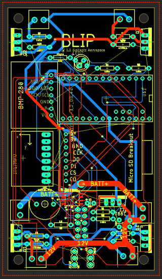
I recently bought a new teensy 3.2, and when I connected it to power, it blinked orange as it's supposed to. This satisfied me, so I soldered it onto the board I had made(it was the last piece to be soldered). Once I had done this, I plugged it in and it did not blink. I tried loading a different program, but when I pressed the program mode button on the teensy, it didn't turn on. I tried using a whole lot of different USB cords, and none worked. I desoldered it to test, and it did work, and I reset it by pressing the button down while plugging it in. So I resoldered it and tested it again with the same results.

Does anyone have any solutions for this?

Thanks a ton!
 
Sure sounds like Teensy is working fine and something about your custom circuit board is interfering.


Does anyone have any solutions for this?

You're basically asking for blind guess solutions to a problem with a custom PCB we can't see and know nothing about.

So, guess #1 is maybe it's drawing too much current or shorting 5V power? Or 3.3V power. To test, measure these voltages (with negative multimeter lead on GND) on Teensy before plugging into your circuit board. Then measure while on the board. They should be basically the same if your board isn't drawing too much current.
 
Sure sounds like Teensy is working fine and something about your custom circuit board is interfering.


You're basically asking for blind guess solutions to a problem with a custom PCB we can't see and know nothing about.

So, guess #1 is maybe it's drawing too much current or shorting 5V power? Or 3.3V power. To test, measure these voltages (with negative multimeter lead on GND) on Teensy before plugging into your circuit board. Then measure while on the board. They should be basically the same if your board isn't drawing too much current.

Okay, would it help if I attached the PCB file?
 
Could you also send the schematic [.sch file]? Or preferably the whole Eagle project?
Findings issues from only the .brd is nearly impossible...

Capture.PNG

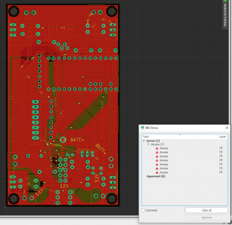
By the way: I see a whole bunch of not routed airwires...

Paul
 
Was able to open your project.
It complained about some missing libraries though.
Even with hitting the ratsnest button and filling in the copper planes, it still complains about airwires:

Capture.PNG

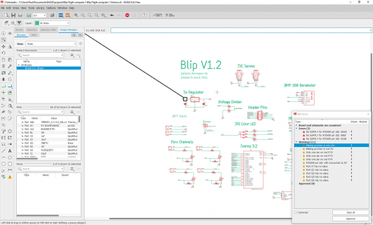
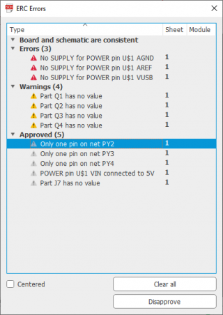
Also the schematic has some errors:

Untitled.png

Are you sure that all the planes are connected to each other? For example: is the +5V plane contiguous such that all the 5V pins of the different components are indeed connected?
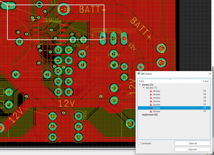
I'm specifically looking at this error:

Capture2.PNG

Those +5V pins don't seem to be connected...

Paul
 
Yeah, the two unrouted airwires that show up on your last image show up for me, but the rest don't. So, you think these are the issues? If I fix and reorder the PCB, and resolder it, you think that'll make it work?

Also, How do you think I should fix the ratsnest not working? Im new to eagle and electronics(that's probably obvious), so I'm not quite sure how to do that.

Thanks a ton for your help!
 
Last edited:
Yes, those airwires are really showing an issue: Eagle tells you that those pins are not [yet] electrically connected.

But before reordering the PCB, I first would measure [using an ohm meter] whether these pins are indeed not connected by the same copper plane. If not connected, then just solder a wire between those 2 points to connect the planes.

I'm surprised that you don't see a longer list of airwires like I see.
For example: on the backplane I see this small copper plane [purple colored by me for clarity]:

Capture.PNG

I'm pretty sure this plane is completely isolated and thus pin "P$2 GND" is not connected to anything. Hence the airwire from that pin to another GND pin.

Paul
 
I just checked again, and I guess I must have missed some because the list shows several I had visually missed. Thanks for your help, I'll fix these and do the things you have said.

I really appreciate it!
 
On the schematic: I see that you use only 1 signal [PY1] to drive all 4 FET's. Is that indeed your intention? I'm asking because you have signals PY2, PY3 & PY4 on Teensy pins.

Untitled.png

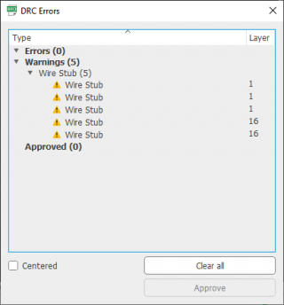
On the board layout, I see 5 wire stub warnings:

Untitled2.png

Although these wire stubs are probably not an issue, I have the habit to always get rid of any warnings. You may want to do as well.
For the rest I don't see any obvious issues.

Paul
 
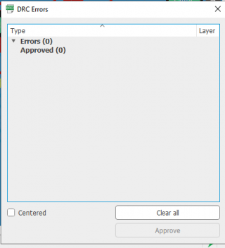
Checked the design once more, but still got those 6 wire stub warnings...

Untitled.jpg

Not sure why I get these warnings and you don't... Anyway, go for it! (standard disclaimers apply though :) )

Success,
Paul
 
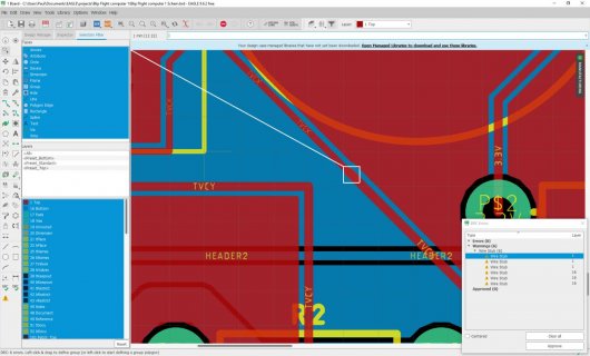
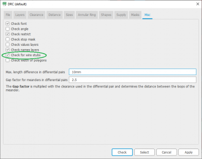
About the wire stub warnings: do you use the default Design Rules provided by Eagle?
Got the wire stub box checked:

Untitled.png

Paul
 
Back
Top