Noticing ~12 kiloohm between ground and 3.3v lines, on Teensy 4.0 & 4.1 unconnected

thank you for your explanations. I'll try swapping my various opamps with this circuit side by side to get a better idea on the precision and the noise.

And thanks for the tip about probe attenuation...I'm finding when just looking at a voltage divider network (of two 1Mohm resistors dividing the 3.3V supply), that switching the 10x attentuation is giving me a little more correct measurement of 1.57 V for midpoint, while not using attenuation on probes gives a too low value of 1.52 V for midpoint.

Basically you almost never use x1 on a x10 probe - primarily because the bandwidth is grossly restricted in x1 mode and the probe tip capacitance is large. x1 is only ever of use for very small signals in a low impedance circuit at low frequency - otherwise x1 is more likely to alter the circuit behaviour than measure it (lots of scope - pun intended - for confusion...)

With a bipolar opamp with say 400nA bias current, even two 100k resistors to the rails gives a DC voltage error of 100k/2 x 0.4µ = 20mV at the input, so you have to watch out for this - though here I think you now are close enough to mid rail to be practical - the last 5--10% isn't necessarily worth worrying about.
 
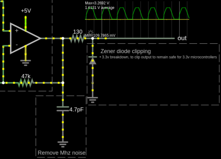
right now I'm looking at different ways to clip the output to never exceed 3.3v, and investigated a few different cheap ways that don't draw a lot of power when not clipping. I'm putting a 130 ohm resistor (which can handle 1 W) at the output and then use a 3.3v zener diode shunted to ground, like:

zener-diode-voltage-limit.png

And even at very large inputs, the output now seems to limit at 3.27v. The zener only turns on when gets close to the limit, and then it completely turns on, and the 130 resistor protects from too much current, which looks like it will be safe if the op amp potentially hypothetically swings to 5v.

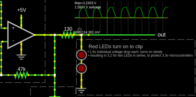
I also find I can do a similar thing by using two red LEDs that convienently have a forward voltage drop of 1.6v each, so when they are in series that is 3.2v drop before they turn on. And the nice thing is they turn on very gently when 3.2v is reached, and the simulation (https://tinyurl.com/y9a74run) shows the max output is 3.23v:

two-red-leds-to-clip.png

I'll still experimenting with resistor values and bais network. I did route the output back into my audio interface (which can handle DC offsets), and the good thing is I can't hear any distortion for medium sized inputs (unless when I push the inputs to cause my output to approach the limits of 0v and 3.3v)...the audio sounds good from 20 Hz to the highest I can hear.

I am having a curious idea to exploit the 1.6v forward voltage drop off these red LEDs to for the biasing network to avoid using large resistors for biasing...
 
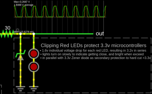
settled on a hybrid solution for the output limiter:
- 2 red diodes (~1.6v each) in series which slowly turn on around 3.2v
- in parallel with 3.3v zener diode which does a much harder cutoff if exceed 3.3v

parallel_leds_and_zener_backup_protection.png
 
The standard protection is Schottky diodes to the rails, which will work even if the Teensy is powered down,
the only thing you need to avoid is the Teensy pin straying outside the Vcc/GND range by more than 0.3V.
The series resistor should be larger like 1k to avoid saturating the opamp - you don't want it to have to go
into overload recovery on clipping, that might exacerbate things like stretching short spikes unnecessarily.

Any clipping-detection or soft clipping can be done in software (which is more configurable), doesn't need
hardware - your scheme only seems to address soft-clipping in one direction too.
 
Back
Top