Noticing ~12 kiloohm between ground and 3.3v lines, on Teensy 4.0 & 4.1 unconnected

ericfont

Well-known member
Noticing ~12 kiloohm between ground and 3.3v lines, on Teensy 4.0 & 4.1 unconnected

I have a working ohmmeter. I have teensy 4.0 or 4.1 unconnected. I connect the - input of my ohmmeter to the teensy ground, and the + input of my ohmmeter to the teensy 3.3v line (either of the 3.3v on Teensy 4.1 too), and I get open circuit, which is good. But when I swap the + & - connections, then with the - input of my ohmmeter connected to either teensy 3.3v line and my ohmmeter + input connected to teensy ground, I then measure 12.35 kohms. I am not sure why there would be a conducting path between those two lines. Again I have the teensy disconnect from anything else.

I also notice that the 3.3V line can't nicely create a 1/2 voltage divider with ground when using resisters greater than about 1 kohm. When I put a resistor from 3.3V to a measuring node, and then put a same sized resistor from that measuring node to teensy's ground, then I would expect the middle measuring note to report 3.3V / 2, or 1.65 V, exactly. While it does that for resistors of size <= 1kohm, however, for larger resistances, particularly 1 Mohm resistors, the voltage I read in the midpoint is much lower. This strange result does seems to be consistent with my earlier measurment with the ohmmeter that there is roughtly 12.35 kohms resistance already between ground and 3.3V.

I do want to know why this ~12.35 kohm resistance is present...and I can't seem to pick out a reason from looking at the schematic.
Unfortunately I want to generate a virtual 1.65v middle reference level, and I was going to use a voltage divider with a couple big ~1 Mohm resistors so I don't draw a lot of current. But that ~12.35 kohms that is already present means I would have to resort to using small resistors which unfortunately drain a lot of power.

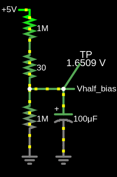
Though at least the 5 V power node doesn't seem to have any resistance to ground, so I can use 3 big identical resistors in series to create a 1.667 voltage reference. But I still want to divide the 3.3V supply to create a 1.65 V reference because the Teensy 4.x comparators can generate that midpoint voltage internally (though the reference manual doesn't mention any way to get those analog references voltages out of the chip). I realize I can make a 50% duty cycle PWM output connected to a big capacitor to ground and it will grab the middle level, though still there will be fluctations in that level I won't like.

So my two big questions are: Why is there this 12.35 kohm resistance between 3.3V and ground. Why does it not appear when I have (-) of my ohm meter connected to ground and (+) connected to 3.3v, but appears with the reverse way. And is there any other good way to get a 1.65v middle reference from the teensy.
 
Active devices are full of pn-junctions so will have typically have different readings in different polarities with a meter, but there's little
meaningful to be deduced other than perhaps there are protection diodes on the pins. What a meter is useful for is spotting a dead-short
between the power rails - that's definitely a fault.

A pair of resistors acting as a divider is commonly used for creating a mid-rail analog bias voltage. When a microcontroller doesn't have
a DAC this is normally used.

What are you wanting to do with the mid-rail voltage BTW?
 
Hi thank you for your answer. What you point out makes sense.

What I wanted to do with the midrange reference was first to center an incomming balanced audio line level voltage to be centered around 1.65V so that it fit in the middle range of the valid analog input range of 0 V to 3.3 V. I had simulated a circuit to do that in circuitjs https://tinyurl.com/ybn6kub9


Simulated_circuit_remove_noise_from_balanced_inputs_and_bias_singled_ended_2022-03-28.jpg

In that circuit i have "Vhalf_bias" as my 1.65v "virtual ground" which is used to bias the incoming audio line. That way I can use a single positive supply op amp to cancel out any noise on the balanced line input.

The big advanced of having exactly 1.65v is because the Teensy has an internal comparator which has 64 internal divisions of 3.3v to use as reference voltage for the comparator. Setting a speicific comparator configuration register with the binary number 32 would result in using that midpoint 1.65v.
And then I have a very solid midpoint reference for detecing things like 0-crossings (or 1.65v crossings) using interrupts from the internal comparator.

Sounds like I will have to use the 5v supply divided by 3 as my reference, although 1.667 V does not exactly equal 1.65 V.
 
I suppose I can get 1.65 from the 5V reference if I use a resistor arrangement like:

1pt65_exactly_with_5volts_.png

And I can even use a trimpot for that 30 ohm resistor to manually calibrate the exact 1.65v midpoint voltage..

(previous image I uploaded earlier mistakenly used 1M in as the top resistor)
 

Attachments

  • 1pt65_exactly_with_5volts.png
    1pt65_exactly_with_5volts.png
    16.1 KB · Views: 24
Last edited:
There's no point calibrating in hardware like this, no precision is needed for the bias point as you ca simply subtract the average from the signal
in software. We are only interested in the AC component of an audio signal after all.

1M resistors would probably force using FET opamps as bias currents are around 0.5µA or so in most bipolar opamps. I'd be inclined to stay to 100k or so
for DC bias resistors in the general case, as this won't cause large output offsets for standard opamps.

Your original circuit has some unusually high values. 10k is fine for most opamp circuits - higher is noisier and more prone to hum pickup too.
The blocking capacitors can be 10 to 22µF with 10k impedances just fine, giving ~1Hz roll off or so. Too large capacitors will mean the circuit takes
forever to stabilize at switch-on.

Its best to have bleed resistors on the inputs to discharge the blocking capacitors to avoid massive thumps on replugging connectors. Also
some RF filtering on audio inputs is pretty much required in these days of mobile phones - 100pF to 1nF ceramic caps to ground on every
input line right on the connector is fairly commonplace to avoid/reduce mobile phone "blippity-blippity-blip" breakthrough.

If the opamp is powered with 5V remember to add protection components so it cannot fry the T4 inputs (which cannot tolerate voltages outside
the supply range).
 
Thank you so much for your comments to improve my circuit.

I will try tweaking around with lower resistors. My original thinking for using big resistor values was to limit power consumption because there would be less current flow... But my knowledge of opamps is limited to the ideal op amp case (I studied computer engineering and our required circuits classes did not go into non-ideal opamps)...and I didn't consider that larger resistors would pick up the noise which I was trying to get rid of!

Out of curious now I've quickly checked on the circuitjs simulator and it seems if I divide all those capacitors and resistors by 10, then I still have a mostly working circuit on first glance (https://tinyurl.com/yb5wq4vy), though I still have some noise to get rid of. And I will look into your suggestions about bleed resistors and RF filtering...I've heard that blippity-blip sound when cell phones are around audio lines and I always wondered what the deal was with that...thanks.

Oh yeah and I did figure out a simple protection on the output by using two Schottky diode...one going from Vout to 3.3v, and the other going from Gnd to Vout, to forcibly clip the outputs to when they exceed the voltage limits by the diode's forward voltage drop..but I will think a bit more and maybe come up with a solution that blinks a red led too and keep it inside the range...maybe there is some sortof diode that acts like a fuse to kill the output too...Much rather loose a diode than a teensy input.
 
I implemented the circuit incorporating your suggestions (circuitjs schmatic url), and used an LM358 for opamp. I am very pleased with the measurement results. In my oscilloscope, the blue signal is the non-inverted original signal, which has a lot of 60 hz power noise and high freqs centered around 69 kHz. And the yellow signal is the cleaned output from my circuit. The bottom of the oscilloscope shows the frequency spectrum.

Here is 0 input signal, and without any cellphone shunt capacitors:
0input_blue-in_yellow-out_no-cellphone-capacitors_20220330_022817.jpg

There is a lot of noise that is gotten rid of simply by putting in the 1 nF shunt capacitors on inputs:
0input_blue-in_yellow-out_1nF-cellphone-capacitors_20220330_022900.jpg

Here is a -24 dB 1kHz sine wave as input signal, providing very clean output:
-24db_1k-sine_20220330_024052.jpg

Here is a -17 dB 1kHz sine wave as input signal, producing some distortion in output:
-17db_1k-sine_some-distortion-bottom-of-sine_and-69khz-noise_20220330_024242.jpg

Here is a -12 dB 1kHz sine wave as input signal, producing a lot of distortion in output, and is the maximum peak-to-peak signal I seem to be able to use with this circuit:
-12db_1k-sine_maximum-amplitude-before-bottom-of-wave-reflects-up_20220330_024436.jpg

If I go louder, here is a -9 dB 1kHz sine wave as input signal, which is almost unrecognizable because the bottom of the sine wave seems to reflect back upwards...probably I'm exceeded some voltage limit:
-9db_1k-sine_lots-of-distortion-bottom-of-wave-reflects-up_20220330_024514.jpg

Other waveforms look fine...here is a 1kHz sqare wave, and all the original frequencies up to 20kHz are passed to output and cleaned:
-20db_1k-square-wave_same-distorion-on-bottom_20220330_024906.jpg

The issue with noise & distortion seems to only affect the bottom of the waveforms, which is interesting and I need to investigate. Also I'm unclear why my waveform is not being centered around 1.65V which is where my voltage divider is supposed to create as a middle reference voltage... Instead it seems the middle voltage is much lower, closer to 1V.

Again any comments on improving circuit design are appreciated. I am very happy with what I have, though I do want to try to maximize the 0V to 3.3V range of the teeny analog inputs.
 
Here is how I laid it out on breadboard. The LM358 opamp has a 10uF decoupling capacitor between its ground and 5v input, since the 5v input I get from teensy/usb is slightly noisey.
160774483-527edfbb-a015-481c-9fd0-83861f6a30af.jpg
 
Well the LM358 has very little bandwidth, many other 5V rail-to-rail opamp are available - the way to find devices
is to the use parametric search facilities on the major component supplier websites...

I'm not sure what circuit you have, but I'm assuming there is an unshielded cable involved, accounting for the severe
mains+noise pick-up. Audio should always be over shielded cable, shield grounded at one end (destination).
 
I'm not sure what circuit you have, but I'm assuming there is an unshielded cable involved, accounting for the severe
mains+noise pick-up. Audio should always be over shielded cable, shield grounded at one end (destination).

Oh wow yeah you are right...the shielding makes a big deal. In my earlier comments I was transferring the audio though a CAT5 cable's differential pair, unshielded. But now I'm going through a shielded TRS 1/4 cable with the shield connected to ground at my teensy breadboard:

IMG_20220330_140514.jpg

And that is producing much cleaner signal even when teensy is unpowered (see next comment with scope snapshot).
 
Here is the oscilloscope view of the incomming positive and negative signal from my audio interface, the same -9dB 1kHz sine wave:

audio through rockville  shielded quarter in cable both pos and negative 20220330_141631.jpg

Note I am not even powering the teensy board yet.
 
And now powering the teensy, in this below screenshot, the blue is the positive version of the signal from the balanced shielded cable I see at my circuit's input, and yellow is my ciruits singled-ended output generated by shifted up to recenter around 1v and subtracting the inputs:

-9db_1k-sine_using-sheilded-cable_20220330.jpg
 
Last edited:
Unfortunately my USB oscilloscope is cheap and has little resolution, but I do see high frequency noise intermittently being added...seems to be 4 frequency peaks at 622 kHz, 691 kHz, 761 kHz, 830 kHz in the spectrum here:

-9dB-sine-shows-high-freq-622kHz-noise-spikes_20220330_143249.jpg
 
Well the LM358 has very little bandwidth, many other 5V rail-to-rail opamp are available - the way to find devices
is to the use parametric search facilities on the major component supplier websites...

While I know how to do parameteric search on major componet websites, my problem is I don't know what is the importance of any of the parameters, lol. Other than basic things like the supply voltage range and input & output voltage range. I did quickly read about the bandwidth and read the Wikipedia on how it relates to the "gain-bandwidth product", but my quick conclusion is that because I'm only concern about audio frequencies ending at 20kHz, and since I don't think I'm acutally doing any amplification (my output signal's amplitude should be exactly twice the input because it subtracts the negative balanced version of the signal from the positive balanced version of the signal), that my primitive limited naive first guess would tell me I just need a bandwidth of at least 20 kHz.
 
Before I order more opamps, I'm going to look through the ones I allready have:

IMG_20220330_150735.jpg

And since you mentioned FET earlier, I'm thinking I'll try this TL084 JFET Quad OpAmp which also works down to single sided supply of 4.5V. (I'm deliberately trying to avoid having to setup a doubled-sided power supply)
 
What I am going to investigate now is why my circuit is centering the signal around 1V, when I *really* want it centered around 1.65V so as to maximize the teensy analog input range. For example, here is a -9dB 1kHz sine wave added to a -9dB 100Hz triangle wave, and the bottom of it clips because the omp amp can only go down to ground:

-9db-1kHz-sine_plus_-9db-100Hz-triangel_clipping_20220330_153118.jpg
 
when I tap my Vhalf_bias node with an osciliscope probe, I see it starts of around 1.08V and then slowly dropps down the longer I have my probe on it. The probe does have a 1 Mohm resistance, so that would explain why the bias voltage drops down... Maybe the fact that I'm using resistors to create the bias voltage is part of the problem...maybe I should use another system like a zener diode or some type of simple voltage regulator to create a 1.65V bias.
 
Seems if I lower the resistors used to create my voltage divider from two 1Mohm resistors to now two 100 kohm resisotrs, now the vhalf_bias doesn't drop so low...though still only 1.40V when I want it to be 1.65 V. But at least now I can send a 2.74 Vpp signal centered around 1.40 V without clipping, though I still have .5V of headroom above I want to use...

Here is snapshot of trangle wave plus sine wave at this 2.75 Vpp level:

square-wave-pluts-triangle-max-2pt75Vpp_offset_1pt4v_20220330_155033.jpg
 
Earlier I said they two inputs subtract and add bias, but i think what really goes on is they subtract and then have an amplitude of half of the amplitude of one of the originals. And it isn't quite a half...it is more like 2.18/4.28 or 50.9% of the original amplitude...I think I need to correct something to make it exactly 50%.

Here the positive balanced signal of blue input from audio interface is 4.28 Vpp and my yellow output is 2.18 Vpp:

4pt28Vpp-input_produces_2pt18Vpp-output.jpg
 
While I know how to do parameteric search on major componet websites, my problem is I don't know what is the importance of any of the parameters, lol. Other than basic things like the supply voltage range and input & output voltage range.
Its worth learning some of the important ones - there's probably some good tutorials out there about opamps, I'm pretty sure Dave Jones at EEVBlog
has one.
I did quickly read about the bandwidth and read the Wikipedia on how it relates to the "gain-bandwidth product", but my quick conclusion is that because I'm only concern about audio frequencies ending at 20kHz, and since I don't think I'm acutally doing any amplification (my output signal's amplitude should be exactly twice the input because it subtracts the negative balanced version of the signal from the positive balanced version of the signal), that my primitive limited naive first guess would tell me I just need a bandwidth of at least 20 kHz.

Opamps trade raw gain for precision/accuracy, so if you want good precision (low distortion), you need a lot of gain across the entire audio
band, so something more like 10MHz to 30MHz gain-bandwidth product is typically appropriate for audio, since you are trying to keep distortion
low all the way upto 10kHz (above that and harmonics are inaudible). Say you want < 0.01% distortion, that takes lots of open
loop gain to achieve, and that has to be open loop gain at 10kHz. So the gain-bandwidth product needs to be some large number times
10kHz.
 
As I said in reply #5 bipolar-input opamps need smaller values of bias resistor than 1M. I recommended 100k as a maximum for use
with bipolar. With 1M you'd need FET-input opamps for sensible behaviour as they only have a few pA of bias current rather than
100's of nA

If you 'scope probe is a x10 type, leave it switched to x10 setting so its much less likely to load the circuit you are measuring
(and get full probe bandwidth too).
 
thank you for your explanations. I'll try swapping my various opamps with this circuit side by side to get a better idea on the precision and the noise.

And thanks for the tip about probe attenuation...I'm finding when just looking at a voltage divider network (of two 1Mohm resistors dividing the 3.3V supply), that switching the 10x attentuation is giving me a little more correct measurement of 1.57 V for midpoint, while not using attenuation on probes gives a too low value of 1.52 V for midpoint.
 
tweaking around some resistor values (circuitjs: https://tinyurl.com/ybgkx35n), now using 510 ohm in non-inverting and 47 k ohm in inverting feedback, I can seem to get a Vpeak-to-peak of 2.82, with the max value around 2.85V and the lowest around 0.03 V. And looks pretty clean (the yellow is what my circuit produces, the blue is the non-inverting input):

max-range_2pt82Vpp_20220330_225450.jpg

Still the average voltage is 1.43 V...haven't quite figured out why that is so much lower than my expected average of 1.65 V which would maximize the range.
 
Back
Top