Teensy 4.1 Reset Button Necessary for Build?

kevin123

New member
Hi, I'm new to Teensy. I've got the 4.1 and am looking to use this chip inside a container that needs to be permanently "potted" with epoxy. This will no longer allow access to the physical reset button. However I do plan to expose the USB connection wire in order to do firmware updates.

Question:

Is this going to be a problem? I've noticed that firmware updates mostly work with the Teensy software / Arduino IDE with no need to press the physical reset button. However it seems occasionally it might be necessary.

Should I go out of my way to install a wired extension in order to expose the reset button outside of the potting compound? Is there any reliable way to avoid this complexity?
 
That button is for 'PROGRAM', not Reset.

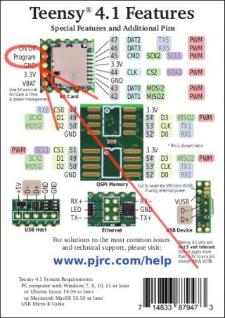
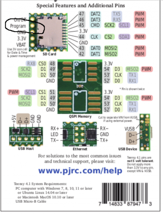
T_4.x's provide a pin hole to duplicate the 'Program' the Button provides.

Without the Program Button, or similar connection, bad code would render the Board unusable.

Would make sense to bring out the Program function wire to allow grounding when required to make the Bootloader active for programming as needed.
 
Without the program button, you'll have to depend on always loading good code which listens for the USB request to go into programming mode. If you ever load a bad program which ignores USB communication for any reason, the hardware will become forever bricked, or at least forever limited to running that particular program.

On the potting process, you might consider using 2 materials (if this isn't already your plan). It's a common practice to first fill the bottom portion having the circuit board with a soft rubber potting compound which avoids mechanically stressing the surface mount components, especially as temperature changes. Or otherwise coat the PCB with soft material to protect the parts. Then the rest is filled with epoxy resin which dries into a hard and tough material for physical protection. If you go with just 1 epoxy material, know that most epoxies put a lot of stress on surface mount parts.
 
Defragster, I can’t seem to find the documentation on the pin hole programming wire. Can you direct me the right place?
 
Defragster, I can’t seem to find the documentation on the pin hole programming wire. Can you direct me the right place?

It's documented on the back side of the pinout reference card which came with your Teensy 4.1.

program_pin.jpg
 
@kevin123 I believe it's active low, so you'll need to pull it to GND to simulate the button press.

I was trying to do a similar thing by controlling the PROGRAM pin from a Pi Zero that was also in the enclosure as a Teensy 4.0. I couldn't get this working successfully and gave up, (rather quickly, so I'm sure it's possible). My setup just uses the teemsy_uploader_cli application with the -s software reboot flag.

Two questions I have - 1. The PROGRAM pin is normally floating, any pros or cons to pulling this up to 3.3V? 2. Are there any particular timing requirements when a. putting in to program mode and b. uploading code?
 
The Program pin should be found to be held HIGH over 3V.

As noted in post#2 - pulling that Program pin to GND for a short time should put the bootloader in control of the Teensy.
 
I was going off the schematic which shows no pull-up, but I did not consider an internal pull-up. I'd guess this is the likely configuration.

Was just going by forum memory ... and a quick check with DMM to see 3V+ on a T_4.1 on the desk.

Indeed, it is somehow high and pulling to GND incites the bootloader to action.

With just a safe Program line presented (though the sealed unit) it could be grounded when needed to USB hood or other common GND.
 
Indeed an internal pullup resistor inside the MKL02 chip is used.

If you wish to add an extra pullup resistor, perhaps to have a lower pullup impedance for noise immunity or just your whim to do so, be sure to connect the pullup resistor to Teensy's 3.3V power. DO NOT connect it to external 3.3V power, such as the Raspberry Pi's 3.3V power.

Teensy 4 has a complex power startup process, which is documented on this page: (scroll down to "Power Up Sequence")

https://www.pjrc.com/store/ic_mkl02_t4.html

The 3.3V power on Teensy 4 starts up at step #6. You don't want an external connection on the Program signal to attempt to feed power into the MKL02's ESD protection diodes during steps 1-5.
 
Thanks for this Paul. I'll have to do some more thinking about this. The problem with the RPi controlling the PROGRAM pin is during boot the RPi pin is low. I was planning a pull-up to 3.3V as an attempt to solve this, but will review your documentation first. Sounds like my idea might be a non-starter. I'll wrap my head around some solutions later.
 
Thanks for this Paul. I'll have to do some more thinking about this. The problem with the RPi controlling the PROGRAM pin is during boot the RPi pin is low. I was planning a pull-up to 3.3V as an attempt to solve this, but will review your documentation first. Sounds like my idea might be a non-starter. I'll wrap my head around some solutions later.

You could add a transistor in place of the switch, which will be high impedance until you need to activate it.
 
You could add a transistor in place of the switch, which will be high impedance until you need to activate it.
Thanks Mark. That's what I was thinking might work, but needed confirmation as I'm no expert on these things.
 
@MarkT - Implemented this and it works just as you would expect. Checking another thing off my to-do list and might actually finish this project. :D
 
Back
Top