Creating a Frequency Sweep to Drive "Speaker"

andrewn2

New member
Hello,

I'm looking to use a Teensy to create a sine wave and sweep through a range of frequencies and drive a Mechanical Wave Driver (basically a long-throw speaker). The exact model is the Pasco SF-9324 (data sheet[pdf]: https://cdn.pasco.com/product_document/Mechanical-Wave-Driver-Manual-SF-9324.pdf). The point of this is to do some vibrations testing and find natural frequencies (they are very low, in the hz range).

It seems like there are multiple ways to accomplish this using Teensy's, and I'm looking for the best way to go about this.

Firstly, using a Teensy 3.1/2/5/6 with and taking advantage of the built-in DAC and analog out pin with an external amplifier (such as the Prop Shield) seems to be the most straightforward way to accomplish this. However, I believe I may run out of pins for use for other purposes in the circuit.

Based on my research, it would appear that another way to do this would be to use PWM, and it would enable me to use the newer 4.0/1, but I struggle to wrap my head around how PWM works to create a sine wave and what other associated circuit parts I would need.

I would appreciate any help with choosing the best path forward, or if there is another way to accomplish this. I'm new to using Teensy's, so any feedback would be super helpful.

Thanks!
 
You could use MQS on Teensy 4.0 / 4.1. MSQ creates a PWM-like output with 352 kHz carrier, so it's easy to low-pass filter the signal to get rid of the fast pulsing. Usually just a resistor and capacitor is enough.

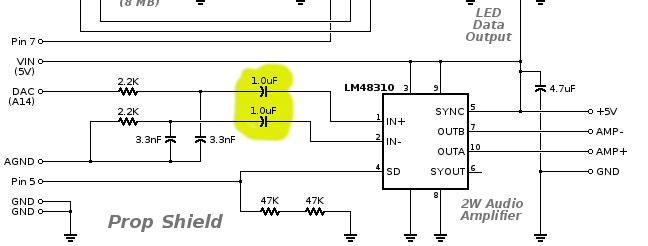
You'll need an amplifier between the low pass filtered signal and driving this device, which electrically is pretty much the same as an ordinary 8 ohm speaker. The challenging part is most amplifiers don't pass extremely low frequencies well below 20 Hz. The Prop Shield is no exception. It might be able to work if you increase these capacitors to support really low frequencies.

sch.png

The Prop Shield already has a 2.2K resistor and 3.3nF capacitor which should block enough of the 352 kHz pulsing, so you can probably just connect the MSQ output pin directly to the Prop Shield pin meant for the DAC output of Teensy 3.2.
 
If you're not familiar with how to do audio on Teensy, this tutorial is the place to start.

https://www.pjrc.com/store/audio_tutorial_kit.html

Maybe skim the first several pages and start at part 2 about the design tool. There's a full walkthrough video which demonstrates every step, in case the written material is unclear. All the examples use I2S for the audio shield. Hopefully once you see how the design tool works, you can find the MQS output and use it instead of I2S. You'll probably draw a very simple design with just the waveform generator and MQS. But if you decide to do more complicated things like create multiple sine waves and mix them together, the design tool is meant to give you the ability to create pretty much anything. As with everything in the design tool, documentation about the specific feature you've clicked appears on the right side panel.
 
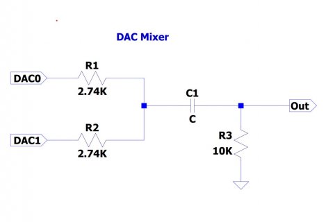
You could use the two DAC outputs of the T3.6 to generate a sine wave with controllable frequency and amplitude in the range from 0.1 to 50Hz. You would have to convert the DAC output to a zero-centered AC waveform for your hardware. That might take an amplifier as well as the following simple circuit:

DAC Mixer.jpg

This circuit allows you to mix the output of DAC0 with the output of DAC1 to generate a sine wave with controllable amplitude. Each DAC sends a sine wave of the desired frequency using an interval timer to send the signal value to the mixer. By sending the output of DAC1 in a variable phase relationship to the signal from DAC0, the sum of the two signals will vary in amplitude as you change the phase relationship.

The two DAC output signals are generated by reading output values from a single lookup table which contains the DAC output value for a single cycle of the Sine output waveform. The output values are sent to DAC0 and DAC1. The DAC1 values are read from the same lookup table, but phase shifted by selecting an output value from a different position in the lookup table.

Here's the code for my demo program:
Code:
/**********************************************
   Generate a low-frequency sine wave and
   control frequency and amplitude
   M. Borgerson   5/4/22
***************************************************/
const char compileTime [] = "\n\nAdjustable Sine Output " __DATE__ " " __TIME__;
const int irqmarkpin  = 32;

// Table size should be a power of 2
// A table size of 1024 is suitable for about 0.5 to 30 Hz
// A table size of 256 is good for 0.5 to ~100Hz
// Smaller tables have bigger jumps at each DAC change.
#define TABLESIZE 256

#define IRQMARKHI digitalWriteFast(irqmarkpin, HIGH);
#define IRQMARKLO digitalWriteFast(irqmarkpin, LOW);

uint16_t sinetable[TABLESIZE];

//   The table is filled with DAC counts for each time
//   step in a complete sine wave.   The DAC counts
//   are limited to 2000 counts above and 2000 counts
//   below the center point of 2048 counts.   This
//   keeps the output values 24 counts from the zero
//   maximum values.
void FillSineTable(void) {
  uint16_t idx;
  float theta, sineval, idxf;
  for (idx = 0; idx < TABLESIZE; idx++) {
    idxf = idx;
    theta = 2 * PI * idxf / TABLESIZE;
    sineval = sin(theta);
    sinetable[idx] = 2048 + int(sineval * 2000.0 + 0.5);
  }
}

void ShowSineTable(void) {
  uint16_t idx;
  Serial.print("Sine Wave Lookup Table");
  for (idx = 0; idx < TABLESIZE/2; idx++) {
    if ((idx % 16) == 0) Serial.printf("\n%3u: ", idx);
    Serial.printf(" %4u", sinetable[idx]);
  }
  Serial.println();
}

// the interval timer microseconds for a desired
// output frequency
uint16_t freqToTcount(float freq) {
  float retval;
  float fperiod;
  fperiod = 1.0 / freq;
  retval = 1000000.0 * fperiod / TABLESIZE;
  //if (retval < 10.0) retval = 10;
  if (retval > 65535.0) retval = 65535.0;
  Serial.printf("\nNew requested frequency = %3.1f\n",freq);
  Serial.printf("Timer Interval = %u microSeconds\n", (uint16_t)retval);
  return (uint16_t)retval;
}

IntervalTimer WaveTimer;

void setup() {
  // put your setup code here, to run once:
  delay(2000);
  Serial.begin(9600);
  delay(500);
  Serial.println(compileTime);
  pinMode(irqmarkpin, OUTPUT);  // init IRQ timing pin
  FillSineTable();
  //ShowSineTable();
  // Default reference sets range to 3.3V
  // analogReference(INTERNAL);// internal references sets range to 1.2V
  analogWriteRes(12);  // set analog resolution
  analogWrite(A21, 2048); // Set DACS to mid-scale
  analogWrite(A22, 2048);
  WaveTimer.begin(&WaveIRQH, freqToTcount(5.0));
  Serial.printf("Starting at 5.0Hz with count %u\n", freqToTcount(5.0));
}


// interrupt handler for WaveTimer.
// This handler executes in about 1 microsecond
// on a T3,6 clocked at 180MHz.
volatile uint16_t idx0 = 0;
volatile uint16_t idx1 = 0;
void WaveIRQH(void) {
 // IRQMARKHI
  idx0 = (idx0) & (TABLESIZE - 1); // constrain indices to be
  idx1 = (idx1) & (TABLESIZE - 1); // within the table
  analogWrite(A21, sinetable[idx0++]);
  analogWrite(A22, sinetable[idx1++]);
  //IRQMARKLO
}

void loop() {
  static float sinefrequency = 5.0;
  uint16_t newcount;
  char key;
  // put your main code here, to run repeatedly:
  delay(50);  // Check for commands at 20Hz
  if (Serial.available()) {
    key = Serial.read();
    if (key == 'a')idx1 += 5; // changes amplitude
    if (key == 'f') { // Increase the frequency
      sinefrequency += 0.5;
      newcount = freqToTcount(sinefrequency);
      if (newcount < 10) { 
        // if new interval is less than 10 uSec, updates will take more
        // than 10% of CPU cycles
        sinefrequency = 1.0;
        newcount = freqToTcount(sinefrequency);
        Serial.println("Resetting to 1.0 Hz.");        
      }
      WaveTimer.update(newcount);
      
    }
  }
}

This code demonstrates a basic principle of Teensy programming: Sometimes it is better to use a bit of the abundant memory to use a lookup table rather than calculating values inside an interrupt handler. The size of the lookup table does depend on a number of decisions you make:

1. How much resolution do you need in frequency and amplitude steps.
2. What is the frequency range over which you need to scan.

This algorithm is simplified to the point that the frequency resolution and the amplitude resolution change as you near the limits of frequency and amplitude. You will need more than the half day I've been testing this demo program to make sure the algorithm suits your purpose.
 

Attachments

  • DAC_Mixer.pdf
    137.3 KB · Views: 37
Back
Top