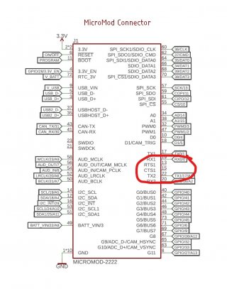
I am using a MicroMod (MM) Teensy in a project. The MM schematic is here:
View attachment MicroMod-Teensy_V1_3.pdf
Thanks to the KurtE spreadsheets, I understand which MM pins are equivalent to which Teensy 4.x pins. But the two pins labeled pin 13 (RTS1) and pin 15 (CTS1) on the MM connector aren't connected to the Teensy in the schematic.
So if I want to use these two pins for Input, what pin numbers do I use in statements like pinMode(xx, Input)?


