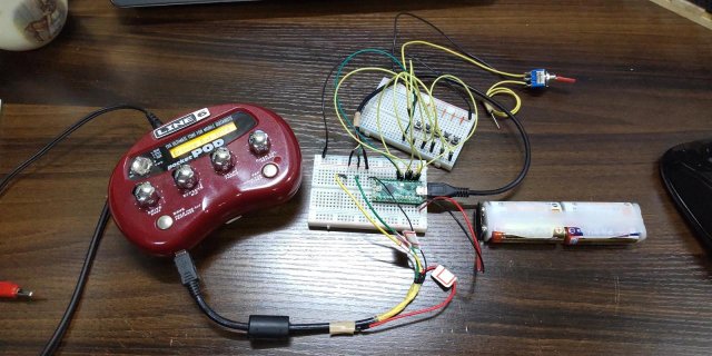
I have problem.(Teensy usb midi running Without PC)

I'm using Google Translate. I think my English is strange, but please forgive me.

I'm a Tenssy beginner.

I want to operate the patch change with a foot switch(Just Tenssy LC.Without PC).
Connect the Tenssy LC to the Line6 pocketPOD(GuitarEffector) with a USB cable and
MIDI program change message for pocketPOD.

The wiring like this:
Tactile Switch1 > D0 and GND
Tactile Switch2 > D1 and GND
Tactile Switch3 > D2 and GND
Tactile Switch4 > D3 and GND
Tactile Switch5 > D4 and GND
Toggle Switch > D5 and GND

I Want to Run ON Batteries(USB Cable Connect Just GND,D+,D-)
RedLine Did not Connect.

4 AA Batteris use.(maybe about 6volts)
AA battery+ > Vin(5V)
AA battery- > GND

Source:
------
#include <Bounce.h>

const int channel = 1;
const int PINS[6] = {0, 1, 2, 3, 4, 5};
const int PIN_COUNT = sizeof(PINS) / sizeof(int);
const int MIDIPG_NUMBERS[PIN_COUNT] = {115, 116, 117, 118, 119, 125};
//115-User1,116-User2,117-User3,118-User4,119-User5,125-Tuner
const int DEBOUNCE_TIME = 5;

Bounce pins[] = {
Bounce(PINS[0], DEBOUNCE_TIME),
Bounce(PINS[1], DEBOUNCE_TIME),
Bounce(PINS[2], DEBOUNCE_TIME),
Bounce(PINS[3], DEBOUNCE_TIME),
Bounce(PINS[4], DEBOUNCE_TIME),
Bounce(PINS[5], DEBOUNCE_TIME)
};

void setup() {
Serial.begin(115200);
// Enable the pins with a pullup.
for (int i=0; i<PIN_COUNT;i++) {
pinMode(PINS, INPUT_PULLUP);
}
}

void loop() {
for (int i=0; i<PIN_COUNT;i++) {
if (pins.update()) {
usbMIDI.sendProgramChange(MIDIPG_NUMBERS,channel);
}
}
while (usbMIDI.read()) {
}
}
------

Hardware connectivity test:
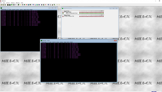
Teensy→PC→MidiOX→pocketPOD

MIDI Input:Teensy MIDI
MIDI Output:Line6 pocketPOD

It worked as expected.
Patch switching was possible with Program Change message on Tactile Switch.
Tactile Switch1-5 > PatchChange(with ProgramChangeMessage115-119).

The tuner could be started by the Program Change message on Toggle Switch.
Toggle Switch > Running Tuner((with ProgramChangeMessage125).

but,,,
Teensy→pocketPOD
Does not work when connected directly.

I want to break this situation, but I don't know how.
Can anyone give me some advice?

Success With PC:
SuccessWithPC.png

It's NotGood:
DSC_0060.jpg
 
Hardware connectivity test:
Teensy→PC→MidiOX→pocketPOD

MIDI Input:Teensy MIDI
MIDI Output:Line6 pocketPOD

It worked as expected.

but,,,
Teensy→pocketPOD
Does not work when connected directly.

Can anyone give me some advice?

@syusaku sano:

Using my best guess from your pictures and your description, I am guessing that the connection between the PC and the Line6 pocketPOD is via USB. If that is the case, you will need to connect a USB cable from the USBhost port on the Teensy (my familiarity is specifically with Teensy 4.0/4.1) to the pocketPOD. I can't tell for certain if that is how your wiring connects. If I've misunderstood the connectivity, please let me know.

Feel free to ask more questions as needed.

Mark J Culross
KD5RXT
 
Thanks for your advice

@syusaku sano:

Using my best guess from your pictures and your description, I am guessing that the connection between the PC and the Line6 pocketPOD is via USB. If that is the case, you will need to connect a USB cable from the USBhost port on the Teensy (my familiarity is specifically with Teensy 4.0/4.1) to the pocketPOD. I can't tell for certain if that is how your wiring connects. If I've misunderstood the connectivity, please let me know.

Feel free to ask more questions as needed.

Mark J Culross
KD5RXT

Hi.Mark.

Thank you for replying to my Question.


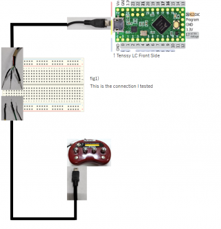
The connection I tested is shown in Fig 1.
fig1.png


Where is my USB host port?
Okay
Take a deep breath and calm down...

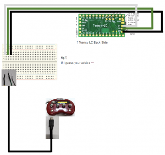
Fig 2 is a guess from your advice.
Is the USB host port on the back side?
(Do not connect the red wire because it uses an external power supply)
fig2.png

Is this correct?
 
You'll need Teensy 3.6 or Teensy 4.1 to do this. Teensy LC doesn't have USB host capability.

It can also be done with Teensy 4.0, but only Teensy 3.6 & 4.1 have the current limit chip and large capacitor needed to USB hot plugging.
 
Thank you for reply

You'll need Teensy 3.6 or Teensy 4.1 to do this. Teensy LC doesn't have USB host capability.

It can also be done with Teensy 4.0, but only Teensy 3.6 & 4.1 have the current limit chip and large capacitor needed to USB hot plugging.

Good evening Paul.

Thank you for answering.

OK.I understand that this hardware cannot do it.

I consider purchasing 3.6, 4.0, 4.1

or

Is it possible with a USB Host shield?

Can you tell me the link of the USBHost shield?
 
Is it possible with a USB Host shield?

It should be possible. But USB host shields communicating over SPI tend to have much lower performance.

The USB host port on Teensy 4.1 and 3.6 supports 480 and 12 MBit USB speeds and the data transfer uses very efficient bus master DMA into memory. Performance is so much better than the SPI-based shields.


Can you tell me the link of the USBHost shield?

Sadly, almost all I have seen appear to be poorly designed. None (which I have seen) have a current limit switch like we use on Teensy 3.6 & 4.1 to support hot plugging. Some people have mentioned cheap Chinese counterfeits of the original from Oleg (the original author of the USB host shield library) with wrong documentation or pins mis-labeled. Maybe there are some good ones out there?
 
Just to expand on what I posted above:
In fact I was so impressed I ordered one for myself - the Thumb Drive Version


USB devices turned into serial devices
For using them with Arduino, etc.
(filename: iva402UsbHost.htm)
Wouldn't it be neat if you could connect a MIDI device to an Arduino or some other microprocessor? Or use a USB keyboard to "talk to" an Arduino?


You can! Not hard. Not expensive. And those aren't the only USB devices the device discussed here can connectto other electronics.

The device is the . It is the Hobbytronics.co.uk USB Host Controller.

For £16.20, plus reasonable p&p, 8/20 you can connect Midi devices, USB keyboards, FTDI serial-from-USB interfaces. You can use a flash memory stick (aka "thumb drive") into you Arduino. (For reading or writing.)

And more.

And this isn't just for the hobbyist. People building "plug and play" systems for commercial purposes find the modules save them development headaches. Why reinvent a wheel?
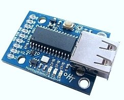
z1.jpg
But I get ahead of myself!
In my view USB in general is the best thing since sliced bread. If you weren't involved with computers before USB came along, be grateful. Very grateful.

But USB is generally used by people on "big", "grown up" computers.

"What's the Hobbytronics gizmo good for??", I hear you wail.

It let's the people who work (or play!) with microprocessors such as the Arduino access the convenience of USB. The Host Controller lets any electronics that can "talk" TTL serial communicate with a wide selection of USB devices.
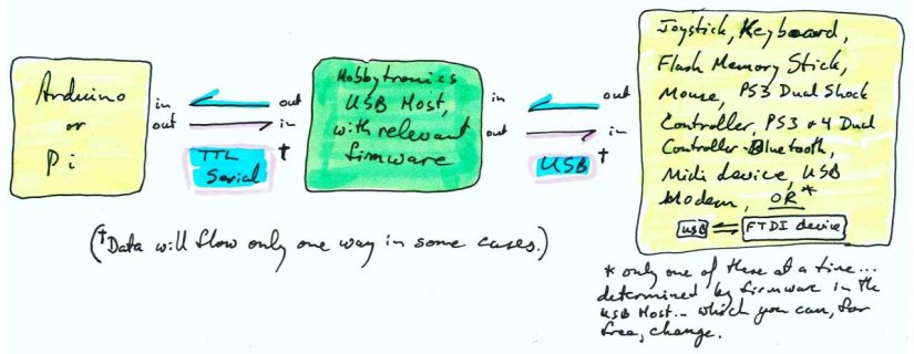
z2.jpg
There's a good summary the different things the board can serve at the main Hobbytronics page for the USB Host Controller... and that page also has links to take you to the individual pages discussing each firmware package's details. Those pages cover technical details- they aren't just sales pitches. Someone spent a lot of time on those pages. Read them, if you are trying to use the controller.

Understand this...
One Board (hardware) / Many Devices (firmware)
When you order one of these, you specify how you want it configured, i.e. what firmware you want loaded into it before it is sent to you.

And that firmware determines what the board does... but only for as long as you want to use your board that way.

You can (for free) change (yourself) what the board does! By changing the firmware in it, you "turn it into" a "different device".

Change the firmware, and the same bit of hardware does a different job. The whole "menu" of alternate firmware is online. I downloaded all the packages when I ordered my first controller. (Have a look at the list above for the different wants the board can gratify.)

Changing the firmware may be a new skill to master, but there is very good guidance on the Hobbytronics website. No special hardware is needed.

What started life as, say, an interface for a Midi device can "become", say, an interface to a USB keyboard or USB memory sticks.

Executive summary of the section above: the firmware is free, and you can change what's in your board

Pins
The board has nine pins. Some of them always have the same purpose. The role of others changes depending on what firmware is loaded.
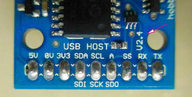
z3.jpg
The following is NOT in the sequence of the pins on the board
"0V": the "ground" pin. This must be connected to the "zero volts" side of your source of voltage for the board, and it will be connected to the ground of everything the USB plug is connected to. (Nothing new here. Except in special cases, where you are deliberately seeking isolation (and go to some trouble to achieve it!), you want the grounds of all parts of your project connected. (This is one of those "everyone knows" things that often cause problems for budding electronic engineers.)

"3v3": This pin provides to you a source of 3v3. If you want 3v3 for some of the circuits you are connecting to the board, you can connect them to this pin. Do not connect circuits which would need more than 250 mA. (From what I've just said, I hope it is obvious that this pin does not have to be connected to anything. Many pins need no connection.)

That's all of the pins that always have the same role, regardless of the firmware is in the device. What the other pins do will be discussed shortly, but the excellent documentation at the Hobbytronics pages would actually be a better source for you. There's one for each of the firmware packages.

---
Apart from the pins for "0v" and "5v", which must always be used as above, you can... and should... just leave other pins connected to nothing, unless you know you need to connect them for some purpose.

In every case, at least one more pin will be in use. But in some cases, only one more pin needs connecting to anything.

"Rx/ Tx": In almost every case, something comes from the attached USB device. Usually, it is passed on as a stream of serial data. That will data leave the Hobbytronics Host Controller via the Controller's "Tx" pin. (Sometimes though, the data is present as the state of pin. (High or low. For example, when the Host Controller has the firmware that makes it an interface for USB keyboards, the "SS" pin will be high when a key is pressed, low when not. (With an Arduino, don't worry about having to "watch" the main input "continuously". Although there is not handshaking, the Arduino has a buffer for incoming serial data. The data is captured and waits in a queue until it is convenient for you to deal with it.)))

The "Rx" pin is for inputs to the board... not always for passing on to the attached USB device. For instance, if you are using the firmware that makes the board a keyboard interface, the microcontroller can tell the board to use a different baud rate. (That is an optional matter... you can just "fall in with" the board's default data rate, unless you want to change the baud rate.)

"SS": This isn't always used. In the cases I've noticed, it is used for signals to the microprocessor. For instance, with the keyboard interface, SS goes high when a key pressed, low when released. Don't assume it will always be an output. Read the excellent documentation at the Hobbytronics pages. (Have I mentioned this?)

"SDA", "SCL", "A": These are used less frequently. When they are, their roles are explained in the Hobbytronics page for the firmware concerned. Don't worry about the fact that they have alternate names ("SDI", "SCK", "SDO").

As I said- there's a good summary the different things the board can be... (Midi interface, Keyboard, Flash drive...) at the main Hobbytronics page for the USB Host Controller... and that page also has links to take you to the individual pages discussing each firmware package's details. Technical details- not just sales pitches!

It is TIME (and the date) to discuss another feature
Ever tried to make a "time of day" clock with an Arduino? WHAT were they thinking (long, LONG before Arduinos were around) when "they" decided a day has 24 hours, an hour 60 minutes? And don't get me started on calendars! (While I'm at it... did you know that "seconds" were once divided into 60 "thirds"? I guess that's where the name "seconds" came from here. But the fact that "a third" was a sixtieth of a second must have been hard on kids just learning about fractions in general.)

How did I get off on this digression? The answer is:

The USB Host Controller has a "bonus" feature: It offers Time of Day Clock and Calendar services.

The host controller... whichever firmware you have loaded... is an RTC. You've heard of RTCs? They are "real time clocks", which often means clock-and-calendar... and it does in this case. The Hobbytronics USB Host Controller gives you easy access to the current time of day, and the date.

Now... don't get too excited... it isn't an all singing, all dancing solution.

You must somehow "re-set" the clock each time the device powers up. (There are various ways to do this... both manual and electronic.) But once initialized, the documentation claims that the RTC should be accurate to within a few seconds per day. Details of using the clock are in the Hobbytronics documentation for the Flash Memory Stick firmware.

Two "gotchas"
First "gotcha"
Well.. a "non-gotcha", actually.

This board doesn't care if you are working with 3v3 or with 5v. Other than needing 5v supplied to it, for it to do its thing.

The inputs to the host controller will tolerate 5v, but will also see 3v3 levels as "on".

The outputs are capable of driving the inputs of both 5v and 3v3 devices.

Do not assume that all electronics are this forgiving! Mix and match the wrong pair of devices, one 5v, the other 3v3, and you will permanently damage one or both of them. (I suppose this is the place my lawyer would like me to say that while I hope you find what's here useful, I warrantee nothing and accept no responsibility at all anything you do (or don't do) after reading any of my pages.

Second "gotcha"
Forgive me if to you the following is obvious. It isn't obvious to everyone!

This a little "gotcha" that has plagued me for years- specifically in this area, and more generally...

When you are thinking about connecting things, the DIRECTION of data flow is important. Duh. But I get confused. As follows, I think...

Take a keyboard as an example.

When you press a key, the electronics in the keyboard creates what is output from the point of view of the keyboard, but input from the point of view of the thing it is plugged into.

Details of one particular firmware choice- Flash Memory Stick
"Flash Memory Stick"? You know these things! Though maybe by a different name? "Thumb Drive"? The "thing" that replaced floppy disks? About the size of your thumb, when they first came out? You plug them in, and then you can read files from them, write files to them. And there are things that work like a memory stick, but you stick an SD card (or similar) into them to provide the "memory". (More properly called "storage" by the way, but whatever, ya' know. Like "you got this, Man" (or WOman), I hope?)

How do you "do storage" across a serial link??

Here's where if you do remember the bad old days before USB you have an advantage.

Even before "before USB", there was "before the Mac and Windows". A GUI-less world. (And it was a nicer place, in some ways.)

If you wanted to save a file, instead of clicking a "Save" button, you typed (gasp) "Save MyFile.txt".

To see what was on a storage device, e.g. a floppy disc, you typed "DIR". And a list of the files appeared on your screen.

To create a folder... they were called directories... you typed "MD HobbytronicsFirmware" for Make Directory.

And so on. And that's exactly how you work with a memory stick, through the Hobbytronics USB Host Controller. It will be a "learning experience" for many, but there's no rocket science or flaky stuff.

Questions?
I hope that has been helpful? I hope you will give Hobbytronics a try, some $upport. In a world increasingly monopolized by "the big boys"... with the resultant loss of innovation... the "little people" need you more than ever.

The page in front of you is a completely new page, created 8/20 (during the Days of Covid!), from scratch. After I finished it, I discovered I'd written one like it previously. Argh. You can see my December 2014 of an earlier version of this device, if you like! I guess we can have confidence in the device's maturity! Anyway, if you want more or less what is above again, said differently, maybe covering a few bits I missed here, try the old page. Do you, as I do, find that reading something "twice" helps you catch things you didn't actually understand the first time I read them? (Even though you thought you had.)

Speaking of "little people", * I *, your faithful tutorial author, could use some support too! Please mention this page and my other efforts on social media, in forums, etc?

A few words from the sponsors...
Please get in touch if you discover flaws in this page. Please mention the page's URL. (wywtk.com/ec/iva/iva402UsbHost.htm).

If you found this of interest, please mention in forums, give it a Facebook "like", Google "Plus", or whatever. If you want more of this stuff, help!? There's not much point in me writing these things, if no one feels they are of any use.
 
Last edited by a moderator:
The connection I tested is shown in Fig 1.

Where is my USB host port?

Is the USB host port on the back side?

Is this correct?

Sorry, I overlooked the fact that you are using the Teensy LC, which, as Paul pointed out, does not have the required USBhost port. Sorry that I did not really answer your question completely and/or correctly. Hopefully, the T3.6 or T4.1 will help you to complete your project.

Mark J Culross
KD5RXT
 
In fact I was so impressed I ordered one for myself - the Thumb Drive Version

I'm really curious to hear how usage of this product with Teensy goes. Looks like it's serial command protocol designed around use from a terminal emulator with human readable commands. Is there any sort of code or library meant to run on a microcontroller like Teensy to communicate with it in its serial protocol?

Also curious to hear if it works with USB media larger than 32GB?


EDIT: ah, I see they have 3 example Arduino sketches on this page.

EDIT Again: Looks like they have a page about using the MIDI version with Teensy 3.1.
 
Last edited:
Following on from my previous post, I have downloaded and placed below the Description of the USB Host.

With this device you simply write to a hardware serial port with the USB Host device attached.
As far as I understand Midi, you would write to the serial port as you would write to a Midi port.
This transmission then gets converted to midi by the Midi Host Board and sent to the Midi device.
As far as running off batteries the LC would work fine with this, especially if you use the Snooze
Library, waking the LC up by input port change.
When woken up the LC can send the info to the Midi device and then go back to sleep again.
A slight problem in this is that I don't know how much current the USB Host device consumes.
You could of course turn power off to the USB Host device via a relay controlled by the LC.

The first thing to do is check whether your USB device is compatible with the USB Host device.

If it is you can then get the comms going, before looking at power reduction schemes.

Regards
Bob
USB Host - MIDI device software

USB Host Board - MIDI device
This software allows you to connect a USB midi device to one of our USB Host boards (or IC's) for 2-way communication using the MIDI protocol.

It translates the USB MIDI data packets to/from Serial data packets at the MIDI baud rate of 31250.

This is a free software download for our USB Host Boards and USB Host IC's (SOIC, DIP, SSOP).

Please note: This software is free to download but only works on one of our USB boards or chips which must be bought separately (see below).

To order, simply select which of our boards or IC products you wish to have the software loaded onto. See the USB Host Board and IC product pages for details on pricing and installing this software.

Download Software
Click Here to Download (Version 1.24)
USB Host BoardUSB Host Mini
USB Host Boards USB Host IC SOIC USB Host IC DIP USB Host IC SSOP
USB Host IC's
With this software on one of our USB Host devices you can now communicate with USB MIDI devices using Arduino / Teensy / Raspberry Pi and many other microcontroller boards using the standard MIDI message format.

Use your USB MIDI device without having to connect it to a computer.

Features

  • Convert your USB MIDI device to Serial TTL
  • Operates at 31250 BAUD
  • Override MIDI Channel Number of device

Supported Devices

  • Standard MIDI compliant devices are supported.

We have a list of known supported devices

Un-Supported Devices

  • Some Complex MIDI devices use a built-in USB Hub. These MIDI devices are not supported and will NOT work with our USB Host Boards. You can determine if your device has a built-in hub by running the free Windows program USB Tree Viewer. If, when you plug in your MIDI device it appears as a new Hub plus one or more devices then it will not work.

Connections required for Midi Software
The USB MIDI device must be connected directly to the USB Host, it cannot be connected through a USB Hub.

Serial TTL connections are at 31250 baud

  • 5V power in
  • 0V
  • TX out
  • RX in

Configuration

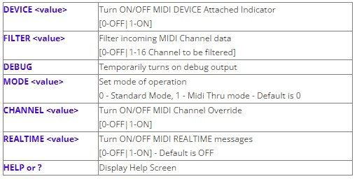
The USB Host Board has the following configuration options available for the MIDI software

[NEW] - As of V1.18 command mode is now inactive by default. The reason is that if you have the board connected to MIDI IN and OUT but no USB MIDI device attached, then serial MIDI data received would be echoed back out on MIDI OUT.

So, in order to get into command mode you must do the following..
1. Boot up the board without a USB MIDI device attached
2. Send two consecutive dollar characters "$$" in the first 10 bytes of serial data. If $$ is not received within the first 10 bytes, a reboot is needed to try command mode again.

The following Commands are available. Connect the board/chip to a suitable serial connection at 31250 BAUD and a Terminal program. The Help screen and configuration settings can only be made when there is no MIDI device attached.

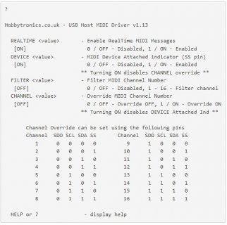
z0.jpg

DEVICE

The DEVICE indicator when turned ON will set the SS pin HIGH when a MIDI device is attached and LOW when removed. This is useful if connecting the board to another microcontroller as it indicates if a MIDI device is attached.

Because the DEVICE option and CHANNEL option use the same SS pin, only one option can be activated.

FILTER

The FILTER option allows you to block ALL incoming MIDI channel data received on the serial RX pin EXCEPT for the MIDI channel selected.

This is useful for MIDI Effects devices which run in OMNI mode only (which means the effect would be applied to ALL channel data)

DEBUG

Temporarily turns on debug output. This is useful if you have a USB MIDI device that is not working. The debug output can be sent to us at Hobbytronics to determine the problem.

MODE

The MODE command is only realy applicable to the MIDI USB to DIN Converter. If you only need to send midi data to the attached MIDI USB device, you can can use the MIDI OUT port as a THRU port

CHANNEL

No configuration needs to be done for normal operation. However, we have added the option to be able to override the outgoing MIDI Channel number. By default this is turned off. This is a very useful feature when connected to a device like the WAV Trigger as it can be used to switch between different set of WAV files - effectively switching instruments.

Turn it on by using the command

CHANNEL 1

The channel number is set using the unused pins on the board. This can be done using a BCD Rotary Switch.
How they are to be set is shown in the Help Screen (as shown below)

z2.jpg

Channel Override can be set using the following pins
Channel SDO SCL SDA SS Channel SDO SCL SDA SS
1 0 0 0 0 9 1 0 0 0
2 0 0 0 1 10 1 0 0 1
3 0 0 1 0 11 1 0 1 0
4 0 0 1 1 12 1 0 1 1
5 0 1 0 0 13 1 1 0 0
6 0 1 0 1 14 1 1 0 1
7 0 1 1 0 15 1 1 1 0
8 0 1 1 1 16 1 1 1 1

HELP or ? - display help

If using the CHANNEL override function, the channel number pins should either be connected to +3.3V or to GND. They should not be left floating.

REALTIME

This option allows you to turn off MIDI Realtime messages. The default is to turn Realtime message OFF

Documents

MIDI message format
Sparkfun MIDI Tutorial
Arduino Board as basic MIDI synthesizer - Create a basic MIDI Synth using an Arduino Board
MIDI Player Tutorial using Teensy 3.1
USB Host Serial MIDI Connections - Connecting the Serial port to serial MIDI devices
MIDI Synth Project - See our project to make a MIDI Synthesizer

Program Updates
To upload the Software to the USB Host Board you will need to use the ds30Loader program. See the USB Host Board product page for more information on this.
 
Last edited:
I'm really curious to hear how usage of this product with Teensy goes. Looks like it's serial command protocol designed around use from a terminal emulator with human readable commands. Is there any sort of code or library meant to run on a microcontroller like Teensy to communicate with it in its serial protocol?

Also curious to hear if it works with USB media larger than 32GB?


EDIT: ah, I see they have 3 example Arduino sketches on this page.

EDIT Again: Looks like they have a page about using the MIDI version with Teensy 3.1.

I'll let you know about the >32GB question. My board should arrive in the next day or so.

As you can see you beat me to it on the other details.
 
Please put these huge copies of the Hobbytronics pages in quote tags. I'm guessing Hobbytronics is probably ok with their info being copied here. Let's at least use the quote feature so people later reading this thread can see the info is copied from somewhere else, rather than wrongly giving casual readers the impression this copied Hobbytronics content was original writing done here on this forum.
 
Sorry, I overlooked the fact that you are using the Teensy LC, which, as Paul pointed out, does not have the required USBhost port. Sorry that I did not really answer your question completely and/or correctly. Hopefully, the T3.6 or T4.1 will help you to complete your project.

Mark J Culross
KD5RXT

Good Morning.Mark.

Please Don't Say Sorry.It's OK.

I will consider other solutions.

Thank you for your awareness.

arigato.
 
Following on from my previous post, I have downloaded and placed below the Description of the USB Host.

With this device you simply write to a hardware serial port with the USB Host device attached.
As far as I understand Midi, you would write to the serial port as you would write to a Midi port.
This transmission then gets converted to midi by the Midi Host Board and sent to the Midi device.
As far as running off batteries the LC would work fine with this, especially if you use the Snooze
Library, waking the LC up by input port change.
When woken up the LC can send the info to the Midi device and then go back to sleep again.
A slight problem in this is that I don't know how much current the USB Host device consumes.
You could of course turn power off to the USB Host device via a relay controlled by the LC.

The first thing to do is check whether your USB device is compatible with the USB Host device.

If it is you can then get the comms going, before looking at power reduction schemes.

Regards
Bob

Hi.Bob.

Thank you for the information.

It's an interesting board.

I will consider buying.
 
It should be possible. But USB host shields communicating over SPI tend to have much lower performance.

The USB host port on Teensy 4.1 and 3.6 supports 480 and 12 MBit USB speeds and the data transfer uses very efficient bus master DMA into memory. Performance is so much better than the SPI-based shields.


Sadly, almost all I have seen appear to be poorly designed. None (which I have seen) have a current limit switch like we use on Teensy 3.6 & 4.1 to support hot plugging. Some people have mentioned cheap Chinese counterfeits of the original from Oleg (the original author of the USB host shield library) with wrong documentation or pins mis-labeled. Maybe there are some good ones out there?

Hi.Paul.

Apparently, I was wrong.

It seems that I read the information of 3.6 or 4.1 at some site and thought that it could be realized by LC.


Thank you for the correct information.
 
Back
Top