Hello PJRC community.
I am attempting to interface the Teensy 4.1 with the evaluation board for the AD4134. The pertinent hardware datasheets are:
Teensy 4.1: https://www.pjrc.com/teensy/IMXRT1060RM_rev2.pdf
AD4134 evaluation board: https://www.mouser.cn/datasheet/2/609/eval_ad4134_ug_2016-2902262.pdf
AD4134 chip: https://www.analog.com/media/en/technical-documentation/data-sheets/ad4134.pdf
LSF-EVM (auto-bidirectional multi-voltage level translators): https://www.ti.com/lit/ug/slvub53/s...url=https%3A%2F%2Fwww.ti.com%2Ftool%2FLSF-EVM
LSF0108 chip: https://www.ti.com/lit/ds/symlink/l...=https%3A%2F%2Fwww.ti.com%2Fproduct%2FLSF0108
I also have an interface board and evaluation software for the ADC which I am using to do troubleshooting, while I work on the Teensy - ADC interface.
SDP-H1: https://www.analog.com/media/en/technical-documentation/user-guides/UG-502.pdf
I am using a benchtop power supply set at 12V to run the ADC evaluation board, and same supply set at 7V to run a 5V regulator for Teensy, and a 3.3V and 1.8V regulator for the voltage translator.
My first milestone is to read a register on the AD4134 using SPI. The code I have uploaded to the Teensy is as follows:
main.cpp
parameters.h
ad4134.h
ad4134.cpp
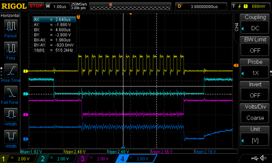
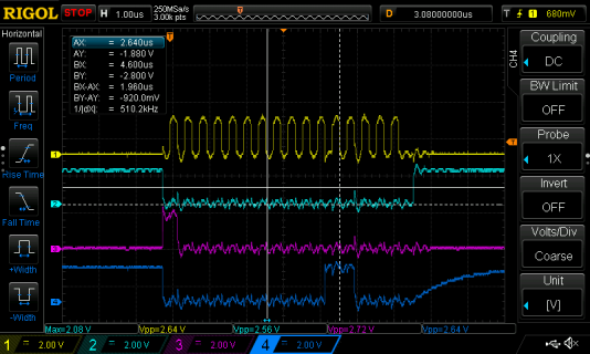
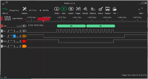
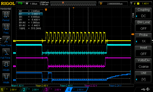
My complication is that when I send a read command (0x80 to read register 0x00) from the Teensy to the ADC and scope the ADC's SDO line, I receive an incorrect response (expect 0x18 but get 0xFF). When I plug in the interface, run the evaluation software, and send same command while scoping the SDO line, I get the correct response (0x18).
Scoping Teensy SPI interface
yellow = CLK
teal = CS
purple = MOSi
blue = MISO

Scoping Interface Board SPI interface
yellow = CLK
teal = CS
purple = SDI
blue = SDO

Please let me know if there is additional information I may provide for troubleshooting. Thank you.
I am attempting to interface the Teensy 4.1 with the evaluation board for the AD4134. The pertinent hardware datasheets are:
Teensy 4.1: https://www.pjrc.com/teensy/IMXRT1060RM_rev2.pdf
AD4134 evaluation board: https://www.mouser.cn/datasheet/2/609/eval_ad4134_ug_2016-2902262.pdf
AD4134 chip: https://www.analog.com/media/en/technical-documentation/data-sheets/ad4134.pdf
LSF-EVM (auto-bidirectional multi-voltage level translators): https://www.ti.com/lit/ug/slvub53/s...url=https%3A%2F%2Fwww.ti.com%2Ftool%2FLSF-EVM
LSF0108 chip: https://www.ti.com/lit/ds/symlink/l...=https%3A%2F%2Fwww.ti.com%2Fproduct%2FLSF0108
I also have an interface board and evaluation software for the ADC which I am using to do troubleshooting, while I work on the Teensy - ADC interface.
SDP-H1: https://www.analog.com/media/en/technical-documentation/user-guides/UG-502.pdf
I am using a benchtop power supply set at 12V to run the ADC evaluation board, and same supply set at 7V to run a 5V regulator for Teensy, and a 3.3V and 1.8V regulator for the voltage translator.
My first milestone is to read a register on the AD4134 using SPI. The code I have uploaded to the Teensy is as follows:
main.cpp
Code:
#include <Arduino.h>
#include "ad4134.h"
#include "parameters.h"

void setup() {
    Serial.begin(9600);
    ad4134_spi_setup();
}

void loop() {
    Serial.println(ad4134_spi_read(0x80 + 0x00));
    delay(1);
}
parameters.h
Code:
#ifndef __PARAMETERS_H__
#define __PARAMETERS_H__

#define AD4134_SPI_CLK_FREQ_HZ	2500000
#define AD4134_SPI_BIT_ORDER_IN	MSBFIRST
#define AD4134_SPI_DATA_MODE_IN	SPI_MODE0
#define AD4134_SPI_CS           10
#define AD4134_SPI_MOSI         11
#define AD4134_SPI_MISO         12
#define AD4134_SPI_SCK          13

#endif /* __PARAMETERS_H__ */
ad4134.h
Code:
#ifndef AD4134_H
#define AD4134_H

#include <Arduino.h>
#include <SPI.h>

/** Setup SPI */
uint32_t ad4134_spi_setup();

/** Read from device. */
uint32_t ad4134_spi_read(uint8_t reg_addr);

#endif //AD4134_H
ad4134.cpp
Code:
#include "ad4134.h"
#include "parameters.h"

/** Setup SPI */
uint32_t ad4134_spi_setup(){
    pinMode(AD4134_SPI_CS, OUTPUT);
    digitalWrite(AD4134_SPI_CS, HIGH);
    SPI.begin();
    return 1;
}

/** Read from device. */
uint32_t ad4134_spi_read(uint8_t reg_addr){

    uint32_t result = 0;
    uint16_t packet = 0;

    packet = reg_addr << 8;

    SPI.beginTransaction(SPISettings(AD4134_SPI_CLK_FREQ_HZ, AD4134_SPI_BIT_ORDER_IN, AD4134_SPI_DATA_MODE_IN));
    digitalWrite(AD4134_SPI_CS, LOW);
    delayMicroseconds(1);
    result = SPI.transfer16(packet);
    delayMicroseconds(1);
    digitalWrite(AD4134_SPI_CS, HIGH);
    SPI.endTransaction();
    return result;
}
My complication is that when I send a read command (0x80 to read register 0x00) from the Teensy to the ADC and scope the ADC's SDO line, I receive an incorrect response (expect 0x18 but get 0xFF). When I plug in the interface, run the evaluation software, and send same command while scoping the SDO line, I get the correct response (0x18).
Scoping Teensy SPI interface
yellow = CLK
teal = CS
purple = MOSi
blue = MISO

Scoping Interface Board SPI interface
yellow = CLK
teal = CS
purple = SDI
blue = SDO

Please let me know if there is additional information I may provide for troubleshooting. Thank you.


