two microcontrollers switching power sources

andi55557

Member
Hi everyone,

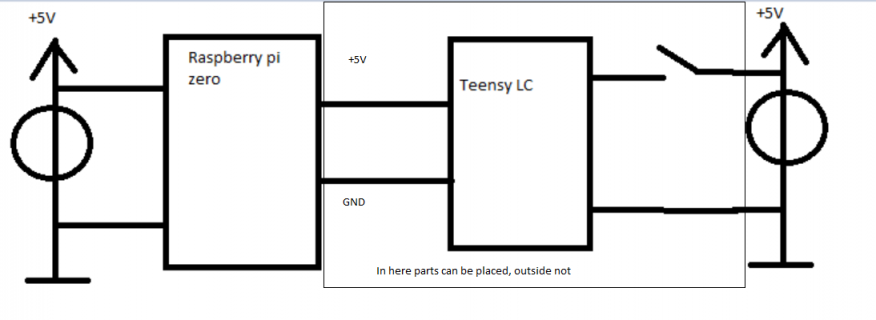
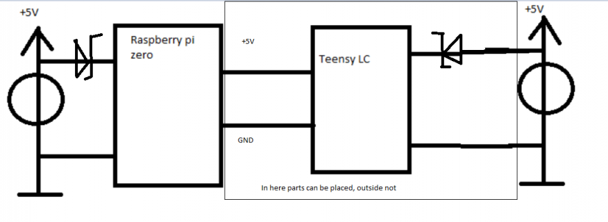
I am planning to build a shield for the raspberry pi zero containing a Teensy LC which is used as a HID.

Problem is: Both have power connections, of which one of them can be turned off or both could be on.

I am not able to put any circuitry like a diode to the power source of the Raspberry pi. I can put whatever in between the Raspberry pi and the teensy and also between the teensy LC and it's power source. Right now the solution is a switch which toggles the power to the teensy.

Is there a way of doing this automatically via logic modules or transistors?

greetings

Andi

Here is a picture of the current concept which i want to replace.
forum.PNG
 
Is there a way of doing this automatically via logic modules or transistors?

greetings

Andi

Here is a picture of the current concept which i want to replace.
View attachment 28965

Andi:

I hope I am understanding your needs correctly. I have a project of my own where I am using a couple of T4.0s connected to a Raspberry Pi. To power the T4.0s, I simply connect a USB cable from one of the USB ports on the Raspberry Pi (one cable for each T4.0) & that way, when the Raspberry Pi is powered-up, the T4.0s are powered as well.

Hope that helps . . .

Mark J Culross
KD5RXT
 
Sorry if I didn't point my problem out clear. There are three cases:
1. The Raspi is powered per usb, the teensy is not
2. The teensy is powered by usb, the Raspi is not
3. both are powered by usb (problem I guess)

Both power sources are 5V. If both are connected it's not good (?) or am I wrong about that?

Andi
 
At least it still is not clear to me on all of your connections.

That is What are the two wires that connect up the LC to the RPI? I assume at least one of them is a common GND?
Do they share a common power pin?
 
Here is the updated sketch. A example solution I found online is placing two schottky diodes on each side between the power source and the microcontroller, but this method is unpractical because i cant place the diode on the raspberry pi side. Anyone has a idea how to have a similar solution with just placing parts in the rectangle in the sketch.

greetings
Andi
 

Attachments

  • forum.PNG
    forum.PNG
    23.9 KB · Views: 16
Last edited:
Here is a quick and ugly sketch of the solution i found online, but thsi method is not practical because i cant place the diode on the raspberry pi side.

greetings, Andi
 

Attachments

  • forum internet solution.png
    forum internet solution.png
    24 KB · Views: 20
Sorry again I am not an EE, so I am probably missing something obvious.

But to me the questions is Why? or more specific, maybe What is the purpose of the Two different power supplies?

Specifically what is the desired results of:

a) Power only turned on the RPI side? I assume the RPI should run. What about the Teensy?
b) Power only on the Teensy side. I assume the teensy should run, what about the RPI?
c) Both, I assume both should run...

If the Answers amount to only the one that has power should run, then simple maybe only partial answer is don't run the 5v line between the two boards....
If RPI should power both, but Teensy only teensy, mayb eschottky Diode on the line between the two

But if the answer is that it should run on either or both, then question still is why not just allow one? If it is for debugging LC, then maybe simply have USB cable where you cut the power wire.

But the part where I am not an EE... My assumption is you are still not telling the full story. That is if it is a shield for the RPI0, I assume there must be other pins connected between the two?

And for example I don't remember if the RPI had any issues of having power connected to some of it's IO pins before there is power connected to the processor. I have used a few other boards in past where the documentation said you were not supposed to... But I never ran into issues with it.

Hi Kurt,

Both devices always need to be powered by +5V, sorry for missing this detail. Also this device is going to be produced a few times and sometimes the power comes from the teensy and sometimes the power comes via the raspberry pi. As far as i know, you should not connect two power sources without anything to one (in this case 2 directly connected) microcontroller(s).

I dont know for sure but as far as I know the problem here would be if the psu's had fluctations in the 5V source maybe one has 5.1V and the other one has 4,9V, you're shorting these with a voltage difference of 0.2V. And all the current passing directly through is probably going to fry the MCU's. Thats what the schottky diodes in recent second picture are for. With those, no current can flow from one psu into the other one. I've already been thinking about a solution like those two diodes but without anything on the raspberry side but cant quite come up with a simple solution. Maybe anyone can think differently about this.

Greetings
Andi


(psu...powers upplying unit, power source, MCU...microcontroller)
 
Back
Top