Teensy 4.1 extraneous GPIO interrupts on opposite edge?

wygonski

Member
I am occaisionally seeing extraneous interrupts occurring on a GPIO pin driven by a 250 Hz pulse train.
I am using Teesyduino 1.56 in PlatformIO on a T4.1.
I have set up the GPIO pin as an input with hysteresis and pulldown:
Code:
pinMode(MAGDATA_PULSE_PIN, INPUT_PULLDOWN);
and this is my ISR:
Code:
void magdataPulseISR( void ) {
  static uint32_t lastTck =magdataPulseTimeUS;
  static uint32_t diffTck = 0;
  static bool firstTime = true;
      DEBUG_GPIO_PIN0_CLEAR;
      magdataPulseTimeUS = microsCount();
      diffTck = magdataPulseTimeUS - lastTck;
      if (!firstTime && (diffTck < 2000000)) {    // trigger on frequency >> 250 Hz
        DEBUG_GPIO_PIN0_SET;
        capturedMagdataPulseTimeUS = magdataPulseTimeUS;        
      } 
      circular_buf_put(&magDataTimeUS_queue, magdataPulseTimeUS);
      magdataPulseIntCount++; 
      firstTime = false;
      lastTck = magdataPulseTimeUS;
      asm volatile ("dsb");      
}
microsCount() is actually using the 600Hz cycle counter to avoid any issue calling micros():
Code:
uint32_t microsCount(void) {
  return ARM_DWT_CYCCNT;
  // WAS: return micros();
}
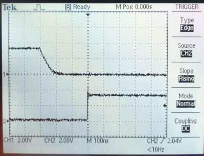
Occaisionally, maybe 3 times in 30 minutes for a 250 Hz pulse train, the ISR apparently triggers also on the falling edge in addition to the rising edge.
This is a scope capture of the unexpected behavior, where the DEBUG_GPIO_PIN0 goes high when the interrupt occurs sooner than expected. The scope is only 100MHz so it may be that I cannot see noise generating another rising edge trigger.
MDP_falling_edge.jpg
The slow transition time of 60 ns exceeds the datasheet stated minimum of 25 ns, and for that reason I added the hysteresis, but it did not affect the symptom.
Any help or comments would be very welcome.
Thanks!
 
Your scope capture shows some coupling between Ch1 and Ch2. For example at the falling edge on Ch1, Ch2 shows a slight bump. After the interrupt, the general noise on Ch1 is mirrored on Ch2. Perhaps your scope ground was too long or maybe something else is going on.

I wonder if your circuit is on a breadboard and the ground runs are too long. Or do you have some relays or motors that could produce noise on the grounds and power rails? Ch1 shows undershoot at the interrupt event, which is strange, which makes me suspicious of the circuit grounds.
 
@rcarr Thanks, I shortened the ground lead and tied it to the host PCB ground plane. No breadboard, but a 2-PCB stack with T4.1 on top. Host PCB is 4-layer with power and ground plane. There are no noise-generating circuits or high-current devices on the host PCB, only power supply and FPGA. I will create a cleaner capture and post it.
 
Here is another scope screenshot with scope probe grounding improved. Interrupt signal driving source (and ground) comes from another PCB over a 18 in. flex cable to the host PCB with Teensy 4.1 stacked on top. Scope ground is on the host PCB ground plane, scope probes (10x) are on the header pins between the T4.1 and host PCB.
MDP_falling_edge_hires2.jpg
Again my initial area of concern was the slow transition time on the top trace, which is the signal triggering the GPIO interrupt. The IMXRT1060 data sheet warned that hysteresis mode should be used for such a signal that exceeded the maximum input transition time of 25 ns (IMXRT1060 Data Sheet section 4.3.2.1 Table 25). From the plot the transition time is approx. 60 ns. Also from the data sheet, hysteresis range is 250 mV for 3V3 supply voltage. However, using hysteresis did not affect the symptom of the interrupt apparently firing on the *falling* edge with the interrupt configured for the rising edge.
Our hardware designer is looking to make circuit improvements to filter the noisy input, but I just wanted to ask the forum whether I am configuring the T4.1 GPIO properly, or if there are any other considerations. (I can "debounce" this input in firmware because we know the pulse train timing, but I wanted to confirm the source of the problem before doing so.)
Thanks!
 

Attachments

  • MDP_falling_edge_2.jpg
    MDP_falling_edge_2.jpg
    116.8 KB · Views: 18
The scope traces look good, I now think your analysis of the issue is correct. May I ask what type of device is driving the signal / why is it slow? Are you relying on just the Teensy internal pulldown to produce the low?
 
The interrupt signal is driven by a Xilinx FPGA. I presume the designer has configured the output pin as high drive and fast(er) transition, but I was not part of the design review. On the IMXRT1060 side, the input is configured with a pulldown and hysteresis in addition to the Schmitt trigger. Perhaps it is worth checking the config registers that this is done properly.
 
Back
Top