GPIO Slew Rate Setting on Teensy 4.1

a_guy_called_tom

Active member
Hi all
I'm using a Teensy 4.1 for an audio device with both an external DAC and an OLED display. I noticed that using the OLED via SPI introduces quite some noise in the audio signal. I would like to try if limiting the slew rate* on some of the SPI pins improves the situation, however i have no clue how to enable/disable the setting on individual pins (and i don't know if its enabled by default or not). Would anyone be able to point me in the right direction with some code snippets?

Many thanks!
Tom


* from the Teensy 4.1 product page:
Slew Rate Limiting
This optional feature greatly reduces high frequency noise when long wires are connected to digital output pins. The rate of voltage change on the pin is slowed. The extra time is only nanoseconds, which is enough to lower undesirable high frequency effects which can cause trouble with long wires.
 
GPIO Slew Rate Setting on Teensy 4.1
I am not sure how to do it either but maybe I can steer you in the right direction at least.

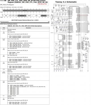
Teensy 4.1 PIN #10 GPIO_B0_00 see schematic.
The issue is I cannot pass argument(!) to IOMUXC_PAD_SRE all I can do is this:
Code:
  // Optimise for 100MHz range, DSE Drive Strength Field, Fast slew rate see pg693 of reference manual. 
  IOMUXC_SW_PAD_CTL_PAD_GPIO_B0_00 |= IOMUXC_PAD_SPEED(1) | IOMUXC_PAD_DSE(4) | IOMUXC_PAD_SRE;
do this after SPI.begin()

Schematic - https://www.pjrc.com/teensy/schematic.html
Reference manual - https://www.pjrc.com/teensy/IMXRT1060RM_rev2.pdf
teensy 4 pad control reg.jpg
 
Hi Chris
many thanks for your help! I was not aware of these macros to configure the pins. Very handy! I did a similar test to try out various different settings for the pins in order to reduce the noise:
Code:
unsigned SPEED_MASK = 0b0000'0000'0000'0000'0001'0000'0010'0000;
IOMUXC_SW_PAD_CTL_PAD_GPIO_B0_02 = SPEED_MASK;

I then just sent out a simple pulse through the pin and observed the signal on a scope: When setting the drive strength field to zero, the signal disappears, so to me it seems that the configuration mechanism works. I then tried to turn on/off the Slew Rate field, but i couldn't see any effect on the scope, the pulse always looked the same (however i guess this could be normal, not quite sure if the change in slope is expected to be seen on a scope)

After doing this basic test, i tried to reconfigure several of the pins connecting to the display directly within the setup function of my audio application (i'm using the adafruit display library so i never start the SPI transaction directly in my code). But regardless of the settings i tried, i never noticed any difference regarding the noise.
Searching the net i found several posts regarding noise and oled displays, and i suspect that main reason for the noise is not the SPI communication with the display but most probably the display itself (most likely the charge-pump that is used internally). I tried different config settings for the display and noticed a change in the noise, however i couldn't fully get rid of it. I might need to do some more trial and error tests or even switch to a display that allows me to fully turn-off the charge-pump.

Anyway, its great that i now know how to finetune the pins using the registers and macros, thanks for pointing this out to me!
Tom
 
Hi Chris and Tom, would you mind explaining in a bit more detail the syntax so that I can change the slew rate and drive strength on specific output pins and please point me to the information i need in the manual ie where the PAD gpio addresses are in the manual? Thanks in advance
Damo
 
Back
Top