Need help with one wire oil pressure sender 80 psi 25-240ohm based.

roarkhen

Active member
Hi all,

First off (I'm a noob) apologies up front. Thanks in advance!

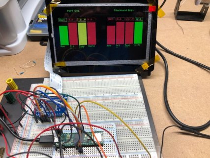
I have a teensy 4.1 that I'm using to develop a Yanmar diesel digital engine panel. I'm going to display RPM, oil pressure, water temp., and alternator voltage. I've got a 7" TFT (RA8875) hooked up already and gauges already working (just feed them random(x, xn)). I've got voltage working via a vcc<25v voltage sensor to A0, and currently trying to get the oil pressure sender working.

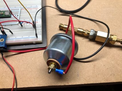
I have a bench test setup w/ the sender hooked up to a bicycle pump (gauge) so I can generate up to about 30psi.

My issue is trying to figure out the hookup. The sender gives a resistance of 25(80psi) to 240(0 psi) range. I understand that I have to convert this to volts somehow. The Interweb shows a lot of discussion on dividers and such, but I'm having trouble applying what I've read.

Assuming I connect teensy 3.3v to the sender (which has a lead pt at the top, and is grounded to the motor in the test I just wire the ground of the bread board to the sender)

where do I attach the A1?
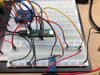
I've tried 330, 220, 100, 50 resistors between the sender lead and the A1 (teensy 3.3 > resistor > sender > teensy gnd).

I've looked at the https://ohmslawcalculator.com/voltage-divider-calculator and used an input of 3.3v R1 of 20, and tried the range of R2 of 1-300 and the voltage out is 0.15-3.094 respectively. So, I tried 20ohms for R1 assuming that the sender represents R2. On the bread board the A1 tap is between the 20ohm resistor and the sender.

Here's a snippet of the data output not much changes when i pump:

<removed bad data... see next post!>


I blatantly ripped this from an example. I understand that R2 is wrong, but I don't know what to set it to as it represents a range?

#define PORT_OIL_PRESSURE_PIN A1
#define STAR_OIL_PRESSURE_PIN A3

float oil_ref_voltage = 3.3;
float R1_oil = 20.0;
float R2_oil = 200.0;

double readOilPressure(ENG_LOC portOStar) {
// Floats for ADC voltage & Input voltage
float adc_oilPressure = 0.0;
float oilPressure = 0.0;
int PIN;

(portOStar == PORT) ? PIN = PORT_OIL_PRESSURE_PIN : PIN = STAR_OIL_PRESSURE_PIN;

// Read the Analog Input
int adc_value = analogRead(PIN);
if (adc_value <= 0) {return 0;}
Serial.print("adc oil value: "); Serial.print(adc_value);

// Determine voltage at ADC input
adc_oilPressure = (adc_value) * ref_voltage / 1023;
Serial.print(", adc oil pressure: "); Serial.print(adc_oilPressure);

// Calculate voltage at divider input
oilPressure = adc_oilPressure / (R2_oil / (R1_oil + R2_oil)) ;
Serial.print(", oilPressure: "); Serial.println(oilPressure);

return oilPressure;
} IMG_1954.jpgIMG_1955.jpgIMG_1956.jpg
 
Last edited:
update: I changed the read value to a float, put ptfe on the junctions for pressure, and now I can hold pressure any where in the range.

at 0psi:
adc oil value: 948.00, adc oil pressure: 4.63, oilPressure: 5.10

at 10psi:
adc oil value: 917.00, adc oil pressure: 4.48, oilPressure: 4.93

at 20psi:
adc oil value: 904.00, adc oil pressure: 4.42, oilPressure: 4.86

at 30psi:
adc oil value: 885.00, adc oil pressure: 4.33, oilPressure: 4.76

At 40psi:
adc oil value: 855.00, adc oil pressure: 4.18, oilPressure: 4.60

At 50psi:
adc oil value: 824.00, adc oil pressure: 4.03, oilPressure: 4.43

At 56psi:
adc oil value: 826.00, adc oil pressure: 4.04, oilPressure: 4.44

At60psi:
adc oil value: 744.00, adc oil pressure: 3.64, oilPressure: 4.00

at 70psi:
adc oil value: 703.00, adc oil pressure: 3.44, oilPressure: 3.78

at 80psi:
adc oil value: 648.00, adc oil pressure: 3.17, oilPressure: 3.48
 
Last edited:
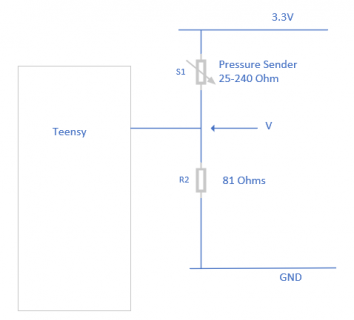
I would suggest that you should wire up the pressure sender something like below:
Pressure Sender Circuit.png
At 0 psi S1 will be 240 Ohms.
Therefore the Current flowing will be (I=V/R) 3.3 / (240 + 81 ) = .01A ( 10mA )
Voltage at V across R2 = ( I * R ) 0.01028 * 81 = 0.8327V

At 80psi S1 will be 25 Ohms.
Therefore the Current flowing will be (I=V/R) 3.3 / (25 + 81 ) = .031A ( 31mA )
Voltage at V across R2 = ( I * R ) 0.031 * 81 = 2.52V

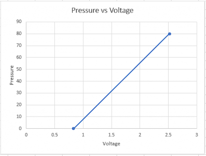
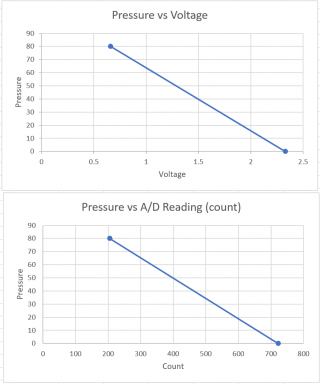
This circuit gives an output shown in the Graph below:
Pressure vs Voltage.png
Pressure = ( V - 0.8327 ) * ( 2.52 - 0.8327 ) = ( V - 0.8327 ) * 1.688988 = 1.688988V - 1.40644

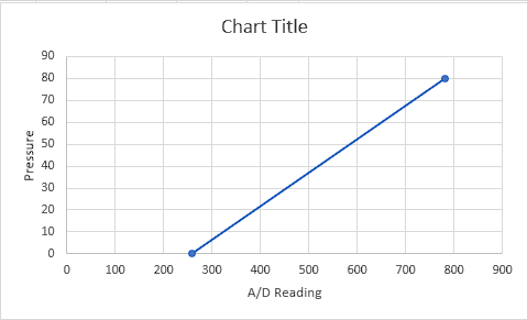
A/D Graph Below:
Pressure vs AtoD Reading.png
Pressure = ( A/D Reading - 258 ) * 80 / ( 782 - 258 ) = ( A/D Reading - 258 ) * 0.1528 = 0.1528* A/D Reading - 39.389
 
Last edited:
Hey, Thanks for the reply. I rigged up your suggestions and came pretty close to a 'valid' output. I'm going to put a better gauge at the 'T', as I believe the bicycle pump gauge is not really very accurate. But the output is certainly in the ball park!
sample:
adc oil value: 497.00, oilPressure: 36.52
adc oil value: 500.00, oilPressure: 36.98
adc oil value: 502.00, oilPressure: 37.28

I have a couple of questions:
1. In your last calc., where does the 258 & 782 come from? (I get that it is a range of possible readings, but how did you determine that?). I would figure the possible range to be either 0-1023, 1-1024? I feel like I'm not understanding something here.
2. Is there a way to flip this circuit so that the the 81 ohm resistor is not at ground of sensor? The reason is that this sensor is screwed into the block of motor so I'm not sure how I would accomplish a resistor here.
3. Why did you choose an 81ohm resistor? I have a bunch of 100ohm resistors, but only 10's under that... weirdly it takes (7) to get ~80ohms. Guessing that's the bread board additive.

Thanks again for the answers!
 
1. In your last calc., where does the 258 & 782 come from? (I get that it is a range of possible readings, but how did you determine that?). I would figure the possible range to be either 0-1023, 1-1024? I feel like I'm not understanding something here.
3.3V will give 1023, therefore 2.52V will give 2.52/3.3*1023. Likewise 0.8327V gives 258.
2. Is there a way to flip this circuit so that the the 81 ohm resistor is not at ground of sensor? The reason is that this sensor is screwed into the block of motor so I'm not sure how I would accomplish a resistor here.
You could swap the Sensor and 81Ohm resistor around but you would have to re-calculate the Voltage/Count codes.
3. Why did you choose an 81ohm resistor? I have a bunch of 100ohm resistors, but only 10's under that... weirdly it takes (7) to get ~80ohms. Guessing that's the bread board additive.
Chose 81Ohms to give the greatest span of readings between 0psi and 80psi, i.e. best resolution.
 
ok. plugging new numbers into the formulas for 100ohm resistor and flipping circuit so 3.3v -> resistor -> sensor -> gnd, and tapping in between resistor and sensor gives counts of 718 (0psi) and 301 (80psi). (i feel like I did the math wrong as your chart shows a lower number closer to 200? Using your ex.

(I=V/R) 3.3 / (240 + 100 ) = .00971A ( 9.7mA ), .971v
.971 / 3.3 * 1023 = 301.01

new calc?
oilPressure = abs(adc_value - 718) * 0.19184);

here are some outputs (new pressure gauge installed w/ T):
adc oil value: 263.00, oilPressure: 87.29 (gauge shows 79)

adc oil value: 314.00, oilPressure: 77.50 (gauge shows 60)

adc oil value: 532.00, oilPressure: 35.68. (gauge shows 30)

adc oil value: 631.00, oilPressure: 16.69 (gauge shows 15)

adc oil value: 726.00, oilPressure: 1.53 (gauge shows 0)
 
The equation will be of a different form. With the Sensor at the top there is a positive slope with a negative intercept. With the Sensor at the bottom you have a negative slope and a positive intercept.
 
yeah I get that. I checked my function against the map() command which does it for you:
map(adc_value, 718, 301, 0, 80)
Only it truncs everything to integers.

Appreciate all the help, thanks! I think my skew is more related to the bread board, accuracy of the guage, and maybe my choice of the 100.

Still curious how you got a number closer to 200 than my 301? Two reasons for the question 1. When I put 200 inplace of my 301 the numbers out are closer to actual gauge pressure. 2. I'm learning here and want to know what my mistake is :)
 
yeah I get that. I checked my function against the map() command which does it for you:
map(adc_value, 718, 301, 0, 80)
Only it truncs everything to integers.
Try casting the value of adc_value to float, then the map() function may perform as you expect
Code:
map((float)adc_value, 718, 301, 0, 80)
 
adc_value was already type float. Tried your suggestion anyway as maybe underneath there was an overloaded function taking type float. Nope, still returns integers.

Thx though :)
 
this is from the docs (I tried your suggestion regardless, and it just returned floats trunc'd to nnn.0):

Notes & Warnings
As previously mentioned, the map() function uses integer math. So fractions might get suppressed due to this. For example, fractions like 3/2, 4/3, 5/4 will all be returned as 1 from the map() function, despite their different actual values. So if your project requires precise calculations (e.g. voltage accurate to 3 decimal places), please consider avoiding map() and implementing the calculations manually in your code yourself.
 
The map() function was improved in TD1.37 to allow use with float & double types. With the release of TD1.54 (see release notes <here>, & search for "map"), the map() function was improved again as follows: "With Teensyduino 1.54, map() now automatically uses floating point math, if the input variable is float or double type."

However, had I gone & looked at this same reference myself, I would have been reminded of the "automatically" part of that latest change (no decimal additions to the range values required) !!

Mark J Culross
KD5RXT
 
yeah I get that. I checked my function against the map() command which does it for you:
map(adc_value, 718, 301, 0, 80)
Only it truncs everything to integers.

Appreciate all the help, thanks! I think my skew is more related to the bread board, accuracy of the guage, and maybe my choice of the 100.

Still curious how you got a number closer to 200 than my 301? Two reasons for the question 1. When I put 200 inplace of my 301 the numbers out are closer to actual gauge pressure. 2. I'm learning here and want to know what my mistake is :)
Here I am, back again, a little late I am afraid.

Ok, P at 80 psi, Sensor resistance (Sr) = 25 Ohm
Current (I) flowing = 3.3V/(25 + 100 ) = 0.0264 Amp
V across Sr = I * Sr = 0.0264 * 25 = 0.66V
3.3V gives 1023 on A/D input = 1023/3.3 count/Volt = 310
0.66V gives 310 * 0.66 = 205 ( Actually 204.6 )

For 0 psi
P at 0 psi, Sensor resistance (Sr) = 240 Ohm
Current (I) flowing = 3.3V/(240 + 100 ) = 0.0097 Amp
V across Sr = I * Sr = 0.0097 * 240 = 2.3294V
3.3V gives 1023 on A/D input = 1023/3.3 count/Volt = 310
2.3294V gives 310 * 2.3294 = 722

To calculate pressure from count this gives:
Slope -0.1547
Intercept 111.72

P=111.72-(0.1547*A/D Reading)
 
Thx, I see where I made my mistake now. I was using the resistor as the multiplier instead of the sensor resistance, giving incorrect range of voltage, which led to incorrect range of AD input.

Awesome, thanks!

Empirically, I found that although the two sensors I have are rated 25-240, they ohm out at ~30-238. Adjusting the calcs gives a +- 2psi accuracy off the gauge. Good enough for me considering the current engine panel has a just an idiot lite w/ alarm when less than 5psi.

Next is the water temp sensor... :)
 
Empirically, I found that although the two sensors I have are rated 25-240, they ohm out at ~30-238. Adjusting the calcs gives a +- 2psi accuracy off the gauge. Good enough for me considering the current engine panel has a just an idiot lite w/ alarm when less than 5psi.
Don't forget to measure the 100 Ohm resistor. With tolerance, it will not be 100 Ohms.
 
Back
Top