Full disclosure: This is my first project on the teensy, so very new to micro controller land. I am an experienced software guy though.
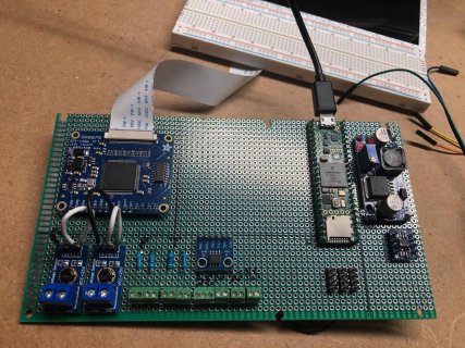
I'm developing a twin engine panel (for a boat), that displays oil pressure, water temp, voltage, and rpm from engine sensors on a 7" TFT via a teensy 4.1. I currently have the pressure, temperature, and voltage parts working on the bench (temp in hot water pan, voltage from battery, pressure rigged to a 'T' and bike pump).
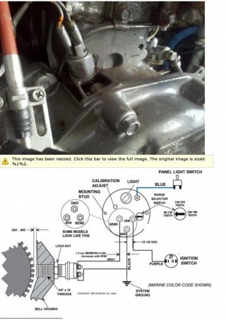
However, I'm at a point where I need to develop the code for the rpm sensor. It's (as I understand it) a magnetic pickup sensor that counts the teeth on the flywheel as the engine runs. I believe it sends increasing voltage pulses down a two wire connection to the existing tachometer.
Since I'm a couple of states away from the boat, I'd like to get the code working for the rpm gauge(s) before next season. I'd like to setup a bench test that would emulate the rpm sensor to allow for me to create and test the code.
Looking for some advice/guidance on what I can use to simulate this? Would a hall effect sensor effectively do the same thing? Meaning would the code be roughly the same except for some minor change to variables, ie. the number of pulses to rpm? Anyway, just hunting for some ideas from the mind share here...
Thx in advance. Here's a pic of the sensor out of the manual. This is an old motor (yanmar 2gm20fc) by the way.
I'm developing a twin engine panel (for a boat), that displays oil pressure, water temp, voltage, and rpm from engine sensors on a 7" TFT via a teensy 4.1. I currently have the pressure, temperature, and voltage parts working on the bench (temp in hot water pan, voltage from battery, pressure rigged to a 'T' and bike pump).
However, I'm at a point where I need to develop the code for the rpm sensor. It's (as I understand it) a magnetic pickup sensor that counts the teeth on the flywheel as the engine runs. I believe it sends increasing voltage pulses down a two wire connection to the existing tachometer.
Since I'm a couple of states away from the boat, I'd like to get the code working for the rpm gauge(s) before next season. I'd like to setup a bench test that would emulate the rpm sensor to allow for me to create and test the code.
Looking for some advice/guidance on what I can use to simulate this? Would a hall effect sensor effectively do the same thing? Meaning would the code be roughly the same except for some minor change to variables, ie. the number of pulses to rpm? Anyway, just hunting for some ideas from the mind share here...
Thx in advance. Here's a pic of the sensor out of the manual. This is an old motor (yanmar 2gm20fc) by the way.
") . What can I use to drive the ncv?
. What can I use to drive the ncv?