Teensy 4.1 Interrupt Problem

MaKettle

Member
I've built a quick test program to determine how quickly the Teensy 4.1 could handle a simple ISR. I've done this many times with UNOs and DUEs , by no means an expert programmer, but this is my first time using a Teensy.
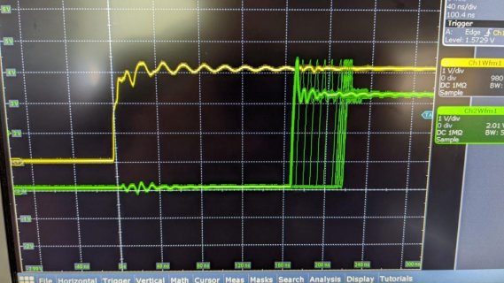
When using a scope to check the Ext clock input vs output, I do see the expected delay as the Teensy handles the interrupt. The problem I've run into is that delay does not remain constant. The delay will be around 160nS for a few seconds, then will have a few longer delays (see traces below) before returning to 160nS. I need the 2 signals to remain phase locked. As shown below , my ext clock is yellow, Teensy output is green, triggered on the ext clock. Its acting like there is some other process running that I'm un aware of... interesting thing is that if I lower the ext clock frequency, then the time between these excursions gets longer , 10s of seconds. Hoping some can see some easy mistake I've made...
Code:
// Test how fast I can use a pin interrupt to 
// trigger on external clock and write port values. 

const int ExtClockPin = 34;           // External clock input

volatile boolean SpeedFlag1 = false;
volatile boolean ExtClkVal = LOW;

void setup() {
  GPIO6_GDIR |= 0x10000;     // 0000 0000 0000 0001 0000 0000 0000 0000‬
                             // Set up pin 19 (GPIO16) as output
  pinMode(ExtClockPin, INPUT);
  attachInterrupt(digitalPinToInterrupt(ExtClockPin), ClkInterrupt, CHANGE);
 }


void ClkInterrupt() {
 ExtClkVal = GPIO7_DR & 0x20000000;        // Read only GPIO7-29
  if (ExtClkVal == LOW)                 // Write to both DACs
    GPIO6_DR &= 0xFFFEFFFF;             // pin 19 low
  else
    GPIO6_DR |= (1 << 16);              // pin 19 high    
}
//void ClkInterrupt() {
//  SpeedFlag1 = !SpeedFlag1;
//  if (SpeedFlag1 == true)
//    GPIO6_DR &= 0xFFFEFFFF;             // pin 19 low
//  else
//    GPIO6_DR |= 0x10000;                // pin 19 high
//}

void loop()
{

}


Scope1.jpg
 
I've built a quick test program to determine how quickly the Teensy 4.1 could handle a simple ISR. I've done this many times with UNOs and DUEs , by no means an expert programmer, but this is my first time using a Teensy.

When using a scope to check the Ext clock input vs output, I do see the expected delay as the Teensy handles the interrupt. The problem I've run into is that delay does not remain constant. The delay will be around 160nS for a few seconds, then will have a few longer delays (see traces below) before returning to 160nS. I need the 2 signals to remain phase locked. As shown below , my ext clock is yellow, Teensy output is green, triggered on the ext clock. Its acting like there is some other process running that I'm un aware of... interesting thing is that if I lower the ext clock frequency, then the time between these excursions gets longer , 10s of seconds. Hoping some can see some easy mistake I've made...

Others know more about this than me, but I think the short answer is the T4 processor is a lot more complex than the one on UNO or DUE. See section 28.2 of the processor reference manual for a description of the ARM M7 core, with super-scalar pipeline (whatever that is), data and instruction caches, etc. There might be a way to disable all caching and make the response more consistent, even if it is slower. You say you need phase lock, so is your goal to generate an output that duplicates your input, with some phase lag? If so, you would probably get less jitter by using an output compare function of a timer. There would be no instructions or data are involved, but even there, the timers are clocked at F_CPU/4, or 150 MHz, and I think that means you could have variability on the order of 1 (maybe +/- 0.5) clock pulse, which would be 6 (or +/- 3) ns.
 
No scope here, though tried to get interrupt response time, in CPU cycles counts, for fun and show some of the code.
> like NVIC_SET_PRIORITY(IRQ_GPIO6789, 30);

Here PWM triggers p#34 wired from p#18, and toggles p#19, so scope on 18/34 and 19 will show the response time.

Response time shown in CPU Cycles with bracketed [Min , Max] each second:
Code:
C:\T_Drive\tCode\T4\InterruptTest\InterruptTest.ino Aug  5 2022 01:55:09
Cnt Diff =56		lCnt=27419041 [56 , 67]
Cnt Diff =56		lCnt=57121456 [56 , 72]
Cnt Diff =56		lCnt=57121448 [56 , 68]
Cnt Diff =56		lCnt=57121453 [56 , 70]
Cnt Diff =61		lCnt=57121453 [61 , 70]
Cnt Diff =61		lCnt=57121454 [61 , 74]
Cnt Diff =56		lCnt=57121450 [56 , 72]
Cnt Diff =56		lCnt=57121453 [56 , 70]
Cnt Diff =61		lCnt=57121451 [61 , 70]
Cnt Diff =56		lCnt=57121453 [56 , 74]
Cnt Diff =56		lCnt=57121452 [56 , 68]
Cnt Diff =61		lCnt=57121452 [61 , 70]
Cnt Diff =61		lCnt=57121454 [61 , 74]
Cnt Diff =56		lCnt=57121454 [56 , 74]
Cnt Diff =56		lCnt=57121450 [56 , 68]
...

Where code is polling _isr response 57M/sec setting the current ARM_DWT_CYCCNT, and the _isr does a difference to what it sees.
> code cheats never leaving loop, and end of that internal loop may HIDE that Min/Max code and the 1 sec printing misses _isr
Code running against 100,000 PWM triggering _isr:
Code:
// Test how fast I can use a pin interrupt to
// trigger on external clock and write port values.
// https://forum.pjrc.com/threads/70821-Teensy-4-1-Interrupt-Problem

const int ExtClockPin = 34;           // External clock input

//volatile boolean SpeedFlag1 = false;
//volatile boolean ExtClkVal = LOW;

void setup() {
  // put your setup code here, to run once:
  Serial.begin(115200);
  while (!Serial && millis() < 4000 );
  Serial.println("\n" __FILE__ " " __DATE__ " " __TIME__);
  NVIC_SET_PRIORITY(IRQ_GPIO6789, 30);
  pinMode(19, OUTPUT);
  analogWriteFrequency(18, 100000); // Choose FREQ and wire pin 34 to 18
  analogWrite(18, 120);
  pinMode(ExtClockPin, INPUT);
  attachInterrupt(ExtClockPin, ClkInterrupt, CHANGE);
}

volatile uint32_t isrCnt;
volatile uint32_t isrHit;
volatile uint32_t DiffCnt;

void ClkInterrupt() {
  DiffCnt = ARM_DWT_CYCCNT - isrCnt;
  isrHit = 1;
  digitalToggle( 19 );
}

uint32_t lCnt = 0;
uint32_t dMin = 2000;
uint32_t dMax = 0;
elapsedMillis oneSec;
void loop()
{
  while (1) {
    while ( 0 == isrHit ) {
      isrCnt = ARM_DWT_CYCCNT;
      lCnt++;
    }
    if ( DiffCnt > dMax ) dMax = DiffCnt;
    if ( DiffCnt < dMax ) dMin = DiffCnt;
    if ( oneSec >= 1000 ) {
      oneSec = 0;
      Serial.printf( "Cnt Diff =%u\t", DiffCnt );
      Serial.printf( "\tlCnt=%u [%u , %u]\n", lCnt, dMin, dMax );
      lCnt = 0;
      dMin = 2000;
      dMax = 0;
    }
    //else  // too many prints at high freq
    //Serial.printf( "Cnt Diff =%u\n", DiffCnt );
    isrHit = 0; // CHEAT to END for high FREQ that above .print code may miss _isr
  }
}
 
@defragster: nice test. I was wondering why the lag time is so huge and had a look at the Teensyduino pin interrupt handler. Looks like there is only one pin interrupt for all pins. Therefore the pin interupt handler needs to check which pin actually generated the interrupt which can take quite some time. In case you know the pin which generates the interrupt beforehand, you can bypass the Teensyduino handler and get a faster reponse:

Here defragsters test code slightly adapted to bypass the stock pin interrupt handler:
Code:
// Test how fast I can use a pin interrupt to
// trigger on external clock and write port values.
// https://forum.pjrc.com/threads/70821-Teensy-4-1-Interrupt-Problem

#include "Arduino.h"
const int ExtClockPin = 34; // External clock input

// volatile boolean SpeedFlag1 = false;
// volatile boolean ExtClkVal = LOW;

volatile uint32_t isrCnt;
volatile uint32_t isrHit;
volatile uint32_t DiffCnt;

volatile uint32_t& portStatusReg = (digitalPinToPortReg(ExtClockPin))[6]; // precalc status reg and mask
uint32_t mask = digitalPinToBitMask(ExtClockPin);

void ClkInterrupt()
{
    portStatusReg = mask;  // we worked around the Teensyduino handler, so we need to reset the status flag ourself

    DiffCnt = ARM_DWT_CYCCNT - isrCnt;
    isrHit  = 1;
    digitalToggleFast(19);

    asm volatile("dsb"); // avoid double calls due to possible bus sync issues
}

void setup()
{
    // put your setup code here, to run once:
    Serial.begin(115200);
    while (!Serial && millis() < 4000)
        ;
    Serial.println("\n" __FILE__ " " __DATE__ " " __TIME__);

    pinMode(19, OUTPUT);
    analogWriteFrequency(18, 100000); // Choose FREQ and wire pin 34 to 18
    analogWrite(18, 120);
    pinMode(ExtClockPin, INPUT);
    attachInterrupt(ExtClockPin, nullptr, CHANGE); // let Teensyduino do the setup work

    attachInterruptVector(IRQ_GPIO6789,ClkInterrupt); // override Teensyduino handler and invoke the callback directly
    NVIC_ENABLE_IRQ(IRQ_GPIO6789);
    NVIC_SET_PRIORITY(IRQ_GPIO6789, 0);  // highest prio, might be good to reduce a bit
}

uint32_t lCnt = 0;
uint32_t dMin = 2000;
uint32_t dMax = 0;
elapsedMillis oneSec;
void loop()
{
    while (1)
    {
        while (0 == isrHit)
        {
            isrCnt = ARM_DWT_CYCCNT;
            lCnt++;
        }
        if (DiffCnt > dMax) dMax = DiffCnt;
        if (DiffCnt < dMax) dMin = DiffCnt;
        if (oneSec >= 1000)
        {
            oneSec = 0;
            Serial.printf("Cnt Diff =%u\t", DiffCnt);
            Serial.printf("\tlCnt=%u [%u , %u]\n", lCnt, dMin, dMax);
            lCnt = 0;
            dMin = 2000;
            dMax = 0;
        }
        // else  // too many prints at high freq
        // Serial.printf( "Cnt Diff =%u\n", DiffCnt );
        isrHit = 0; // CHEAT to END for high FREQ that above .print code may miss _isr
    }
}

Which prints:
Code:
src/main.cpp Aug  5 2022 12:07:42
Cnt Diff =27		lCnt=40121944 [27 , 29]
Cnt Diff =27		lCnt=58571463 [27 , 29]
Cnt Diff =27		lCnt=58571462 [27 , 29]
Cnt Diff =27		lCnt=58571461 [27 , 29]
Cnt Diff =27		lCnt=58571460 [27 , 29]
Cnt Diff =27		lCnt=58571463 [27 , 29]
Cnt Diff =27		lCnt=58571462 [27 , 29]
Cnt Diff =27		lCnt=58571461 [27 , 29]
Cnt Diff =27		lCnt=58571460 [27 , 29]
Cnt Diff =27		lCnt=58571463 [27 , 29]
Cnt Diff =27		lCnt=58571460 [27 , 29]
Cnt Diff =27		lCnt=58571462 [27 , 29]
Cnt Diff =27		lCnt=58588809 [27 , 30]
Cnt Diff =27		lCnt=58571463 [27 , 29]

So, that's 27 cycles from edge to ISR which seems reasonable. I think the remaining jitter is due to DMA activities from the serial printing. Might be interesting to do a version which collects all data whithout printing and print the result after the measurement.
 
You say you need phase lock, so is your goal to generate an output that duplicates your input, with some phase lag?

Sort of... in the end I'll be generating multiple timing signals and data for 2 12bit parallel load DACS, phase adjustment is not important, but stability is. The 60-80ns jitter I saw is unacceptable, 10-20 would be OK.
 
Try setting the interrupt priority to a lower number, using NVIC_SET_PRIORITY

Ahh... this fixed it. I did see references to doing this in the forum, but ignored them thinking I was only using the 1 interrupt ( no serial commands or delays, etc...) and that priority wouldn't matter.

Thanks
 
No scope here, though tried to get interrupt response time, in CPU cycles counts, for fun and show some of the code.
> like NVIC_SET_PRIORITY(IRQ_GPIO6789, 30);

No scope? .... actually using an (unnamed but well respected) scope with really good spec's we had a very difficult time capturing the quick burst of delayed edges, but our tried-and-true Teks caught it every time. Your method is probably better.

Anyway thanks for code
 
@defragster: In case you know the pin which generates the interrupt beforehand, you can bypass the Teensyduino handler and get a faster reponse:
.

I tried adding both methods on my system and found just the opposite, bypassing the handler seems to run a little slower.
NOTE: I only added the lines of code needed to my code to prioritize the interrupt and then to bypass the teensyduino handler, I did not run either defragster's or luni's code in its entirety, therefor no serial output.
NOTE: I also removed the digitalToggleFast() from the ISR and replaced and ran it with matching bit toggling code.
Simply setting the int priority would run at roughly 156nS while setting the priority AND bypassing the teensy handler would run at 172nS . If I then changed the ISR to use the digitalToggleFast() then it ran significantly faster, at 123nS.

I appreciate all the help, Thanks
 
@defragster: nice test. I was wondering why the lag time is so huge and had a look at the Teensyduino pin interrupt handler. ...

Thanks for the nice review! Yes, all pin ports 6,7,8,9 - when 1062 Teensy in FastIO mode - are mapped to one _isr vector.

Code as posted with CHANGE on PWM was running at freq=100K {200K changes/sec}, and times went bad at freq=200K. Doing it with the 'Single Pin' handler lets it run at 200K, goes long at freq=300K. Adding count of _isr 'Hits' seen in tight loop() code showed it missing 2 at freq 100K and here 4 missing at freq=200K:
Code:
C:\T_Drive\tCode\T4\InterruptTest\InterruptTest.ino Aug  5 2022 10:03:41
Cnt Diff =23		lCnt=27302012 [23 , 29] Hits:191494
Cnt Diff =23		lCnt=56995857 [23 , 29] Hits:399996
Cnt Diff =29		lCnt=56995853 [23 , 29] Hits:399996
Cnt Diff =29		lCnt=56995852 [23 , 29] Hits:399996
...

NOTE: Adding that Hits code borders on adding too much time in the loop processing. Moving/adding single instructions can get a SPIKE in the Max time indicated at highest freq test.

No scope? .... actually using an (unnamed but well respected) scope with really good spec's we had a very difficult time capturing the quick burst of delayed edges, but our tried-and-true Teks caught it every time. Your method is probably better.

Anyway thanks for code

Was indicating there is 'No Scope here' to test with ... so wondered if some usable simulation could be done.

Showed "digitalToggle( 19 );" because for testing just the _isr lag/jitter it minimizes the time spent in the _isr, though doesn't show the desired 'port IO'.

Was fun to hack the simulation - nice that @luni verified it as nice test of the issue at hand. Scope testing would remove the 'code testing code' overhead - though the code does have time to track Min/Max to document observed jitter.

Not sure what frequency is in play with the desired _isr Port I/O. Running code here with PWM at 20K it is catching all 40,000 transitions with @lunis's single pin _isr:
Code:
C:\T_Drive\tCode\T4\InterruptTest\InterruptTest.ino Aug  5 2022 10:21:34
Cnt Diff =26		lCnt=59697840 [26 , 29] Hits:39998
Cnt Diff =20		lCnt=59696359 [20 , 29] Hits:40000
Cnt Diff =26		lCnt=59696358 [26 , 29] Hits:40000
...

And using the default IRQ_GPIO6789 code it adds a bit more jitter and overhead
Code:
C:\T_Drive\tCode\T4\InterruptTest\InterruptTest.ino Aug  5 2022 10:28:31
Cnt Diff =60		lCnt=59411281 [60 , 75] Hits:39994
Cnt Diff =62		lCnt=59409556 [62 , 66] Hits:40000
Cnt Diff =59		lCnt=59409555 [59 , 66] Hits:40000
Cnt Diff =64		lCnt=59409555 [64 , 72] Hits:40000
Cnt Diff =62		lCnt=59409550 [62 , 74] Hits:40000
Cnt Diff =63		lCnt=59409555 [63 , 66] Hits:40000
...

There is an alternative to @luni's Single Pin _isr and that is putting the desired pins back into normal/slow IO mode which returns those pins to the single _isr per port. Code would be more responsive, but those pins would have lowered IO speed in some regard.
This code moves to FAST GPIO and - seems there are some posts about undoing this per pin:
Code:
#if defined(__IMXRT1062__)
	// Use fast GPIO6, GPIO7, GPIO8, GPIO9
	IOMUXC_GPR_GPR26 = 0xFFFFFFFF;
	IOMUXC_GPR_GPR27 = 0xFFFFFFFF;
	IOMUXC_GPR_GPR28 = 0xFFFFFFFF;
	IOMUXC_GPR_GPR29 = 0xFFFFFFFF;
#endif
 
Back
Top