Errors Using Wire Library Alongside Audio on Teensy 4.1

grinch

Well-known member
Hi, I'm working on an audio project where I am using an IS31FL3236A I2C LED driver alongside the Teensy 4.1 audio library with the CS42448 TDM codec.

When running my code I get the expected visual behavior, but with a lot of I2C transmit errors, then at a certain point the I2C just stops working entirely and returns an error for every write. I have used the Audio library alongside i2c_t3 with the same LED driver before and this worked really well, but I'm now having to switch over to wire on 4.1 and it's creating a lot of problems.

In order to get around the blocking writes that Wire does I am doing one write every millisecond, and updating the LED buffer every 40 milliseconds (for a refresh rate of 25hz), so that timing critical stuff can happen between writes.

Here is my project code, any idea what might be causing this? Would the Teensy4_i2c library improve this behavior in any way? (wanted to avoid using this because of conflicts with the audio library, but willing to try...):

Code:
#include <Audio.h>
#include <Wire.h>

AudioSynthWaveformSine sine[8];
AudioOutputTDM         tdm_out;
AudioControlCS42448     codec;

AudioConnection pc_out0(sine[0], 0, tdm_out, 0);
AudioConnection pc_out1(sine[1], 0, tdm_out, 2);
AudioConnection pc_out2(sine[2], 0, tdm_out, 4);
AudioConnection pc_out3(sine[3], 0, tdm_out, 6);
AudioConnection pc_out4(sine[4], 0, tdm_out, 8);
AudioConnection pc_out5(sine[5], 0, tdm_out, 10);
AudioConnection pc_out6(sine[6], 0, tdm_out, 12);
AudioConnection pc_out7(sine[7], 0, tdm_out, 14);

#define IS31_ADDR 0x3C
#define EN_PIN 22

uint8_t data_buf[37] = {};
uint8_t led_default[36] = {};

inline void write_is31_byte(uint8_t reg, uint8_t data){
  Wire1.beginTransmission(IS31_ADDR);
  Wire1.write(reg);
  Wire1.write(data);
  int err = Wire1.endTransmission();
  if(err != 0){ Serial.print("I2C_Error: "); Serial.println(err); }
}

inline void write_is31_buffer(uint8_t reg, uint8_t *data, int len){
  for(int i = 0; i < len; ++i){
    write_is31_byte(reg+i, data[i]);
  }
}

inline void write_is31_pwm(uint8_t *data){
  write_is31_buffer(0x01, data, 37);
}

void init_is31( void ){
  pinMode(EN_PIN, OUTPUT);
  digitalWriteFast(EN_PIN, HIGH);
  for(int i = 0; i < 36; ++i){ led_default[i] = 1; }
  delay(10);
  write_is31_byte(0x00, 0x01);
  delay(10);
  write_is31_byte(0x4B, 0x01);
  delay(10);
  write_is31_buffer(0x26, led_default, 36);
  delay(10);
}

void setup() {
  Serial.begin(115200);
  pinMode(LED_BUILTIN, OUTPUT);

  AudioMemory(256);
  codec.enable();
  codec.volume(1);

  for(int i = 0; i < 8; ++i){
    sine[i].amplitude(1);
    sine[i].frequency(100 + i * 50);
  }

  delay(1000);

  Wire1.begin();
  init_is31();
  
  delay(1000);
 
}

int light = 0;
unsigned long led_timer = 0;
unsigned long i2c_timer = 0;
unsigned long update_timer = 0;

int i2c_index = 0;

void loop() {
  
  if(millis() > led_timer + 250){
    led_timer = millis();
    for(int i = 0; i < 36; ++i){
      data_buf[i] = (i == light) ? 255 : random(100);
    }
    data_buf[36] = 0; //update leds register write
    light = (light + 1) % 36;
  }

  if(millis() > update_timer + 40){
    update_timer = millis();
    i2c_index = 0;
  }

  if(millis() != i2c_timer && i2c_index < 37){
    i2c_timer = millis();
    write_is31_byte(0x01 + i2c_index, data_buf[i2c_index]);
    ++i2c_index;
  }
  
}
 
After doing some minor changes to the Wire library to make the errors more human readable I am seeing a lot of I2C error 1 and 2, which point to the following errors in the library. Does this give any clues as to what might be going on?

Specific Errors:
Code:
		// monitor status
		uint32_t status = port->MSR; // pg 2884 & 2891
		if (status & LPI2C_MSR_ALF) {
			port->MCR |= LPI2C_MCR_RTF | LPI2C_MCR_RRF; // clear FIFOs
			return 1;//4; // we lost bus arbitration to another master
		}
		if (status & LPI2C_MSR_NDF) {
			port->MCR |= LPI2C_MCR_RTF | LPI2C_MCR_RRF; // clear FIFOs
			port->MTDR = LPI2C_MTDR_CMD_STOP;
			return 2; // NACK (assume address, TODO: how to tell address from data)
		}

In context of full endTransmission code:

Code:
uint8_t TwoWire::endTransmission(uint8_t sendStop)
{
	uint32_t tx_len = txBufferLength;
	if (!tx_len) return 4; // no address for transmit
	if (!wait_idle()) return 5;//4;
	uint32_t tx_index = 0; // 0=start, 1=addr, 2-(N-1)=data, N=stop
	elapsedMillis timeout = 0;
	while (1) {
		// transmit stuff, if we haven't already
		if (tx_index <= tx_len) {
			uint32_t fifo_used = port->MFSR & 0x07; // pg 2914
			while (fifo_used < 4) {
				if (tx_index == 0) {
					port->MTDR = LPI2C_MTDR_CMD_START | txBuffer[0];
					tx_index = 1;
				} else if (tx_index < tx_len) {
					port->MTDR = LPI2C_MTDR_CMD_TRANSMIT | txBuffer[tx_index++];
				} else {
					if (sendStop) port->MTDR = LPI2C_MTDR_CMD_STOP;
					tx_index++;
					break;
				}
				fifo_used++;
			}
		}
		// monitor status
		uint32_t status = port->MSR; // pg 2884 & 2891
		if (status & LPI2C_MSR_ALF) {
			port->MCR |= LPI2C_MCR_RTF | LPI2C_MCR_RRF; // clear FIFOs
			return 1;//4; // we lost bus arbitration to another master
		}
		if (status & LPI2C_MSR_NDF) {
			port->MCR |= LPI2C_MCR_RTF | LPI2C_MCR_RRF; // clear FIFOs
			port->MTDR = LPI2C_MTDR_CMD_STOP;
			return 2; // NACK (assume address, TODO: how to tell address from data)
		}
		if ((status & LPI2C_MSR_PLTF) || timeout > 50) {
			port->MCR |= LPI2C_MCR_RTF | LPI2C_MCR_RRF; // clear FIFOs
			port->MTDR = LPI2C_MTDR_CMD_STOP; // try to send a stop
			return 3;//4; // clock stretched too long or generic timeout
		}
		// are we done yet?
		if (tx_index > tx_len) {
			uint32_t tx_fifo = port->MFSR & 0x07;
			if (tx_fifo == 0 && ((status & LPI2C_MSR_SDF) || !sendStop)) {
				return 0;
			}
		}
		yield();
	}
}
 
And when the board locks up, it repeated returns the error 3, which is an i2c timeout:

Code:
		if ((status & LPI2C_MSR_PLTF) || timeout > 50) {
			port->MCR |= LPI2C_MCR_RTF | LPI2C_MCR_RRF; // clear FIFOs
			port->MTDR = LPI2C_MTDR_CMD_STOP; // try to send a stop
			return 3;//4; // clock stretched too long or generic timeout
		}
 
Ok, this is a longshot... but try adding a 22pF to 100pF capacitor between the SCL pin and GND. The exact capacitor value doesn't really matter, as long as its good quality ceramic (pretty much all capacitors in this range will be) and the leads are reasonably short. But don't stress an small difference like a 1/4 inch (6 mm) in lead length.

Recently we discovered I2C slave mode was sensitive to high frequency signals like MCLK. With TDM you have that on both MCLK and BCLK. I don't know much about this LED driver chip, but I see it mentions 3 MHz clock, so maybe it's contributing high frequency noise too? Might be a perfect storm of this sort of high frequency coupling. Maybe.

So far this problem has only been confirmed with slave mode. Looks like you're using master mode. I did say it's a longshot, but if you have any spare capacitors in that range, it's worth a quick try. Please let me know if it makes any difference?

Thanks for the reply! Just tried with a 100pf cap and I'm getting the same results. I did find a temporary workaround in code, by resetting the Wire1 object and the IS31 led driver whenever I get a wire error, but would like to find a better solution:

Code:
#include <Audio.h>
#include <Wire.h>

AudioSynthWaveformSine sine[8];
AudioOutputTDM         tdm_out;
AudioControlCS42448     codec;

AudioConnection pc_out0(sine[0], 0, tdm_out, 0);
AudioConnection pc_out1(sine[1], 0, tdm_out, 2);
AudioConnection pc_out2(sine[2], 0, tdm_out, 4);
AudioConnection pc_out3(sine[3], 0, tdm_out, 6);
AudioConnection pc_out4(sine[4], 0, tdm_out, 8);
AudioConnection pc_out5(sine[5], 0, tdm_out, 10);
AudioConnection pc_out6(sine[6], 0, tdm_out, 12);
AudioConnection pc_out7(sine[7], 0, tdm_out, 14);

#define IS31_ADDR 0x3C
#define EN_PIN 22

uint8_t data_buf[37] = {};
uint8_t led_default[36] = {};

inline void write_is31_byte(uint8_t reg, uint8_t data){
  int err = -1;
  while(err != 0){
  
    Wire1.beginTransmission(IS31_ADDR);
    Wire1.write(reg);
    Wire1.write(data);
    
    err = Wire1.endTransmission();
  
    if(err != 0){ Serial.print("I2C_Error: "); Serial.print(err); Serial.print(" - At Timestamp: "); Serial.println(millis());}
    if(err != 0){
      Serial.println("attempting wire reset");
      Wire1.begin();
      Wire1.setClock(400000);
      init_is31();
    }
  }
}

inline void write_is31_buffer(uint8_t reg, uint8_t *data, int len){
  for(int i = 0; i < len; ++i){
    write_is31_byte(reg+i, data[i]);
  }
}

inline void write_is31_pwm(uint8_t *data){
  write_is31_buffer(0x01, data, 37);
}

void init_is31( void ){
  pinMode(EN_PIN, OUTPUT);
  digitalWriteFast(EN_PIN, HIGH);
  for(int i = 0; i < 36; ++i){ led_default[i] = 1; }
  write_is31_byte(0x00, 0x01);
  write_is31_byte(0x4B, 0x01);
  write_is31_buffer(0x26, led_default, 36);
}

void setup() {
  Serial.begin(115200);
  pinMode(LED_BUILTIN, OUTPUT);

  delay(1000);

  Wire1.begin();
  Wire1.setClock(400000); 
  init_is31();
  
  AudioMemory(256);
  codec.enable();
  codec.volume(1);

  for(int i = 0; i < 8; ++i){
    sine[i].amplitude(1);
    sine[i].frequency(100 + i * 50);
  }
 
}

int light = 0;
unsigned long led_timer = 0;
unsigned long i2c_timer = 0;
unsigned long update_timer = 0;
unsigned long run_timer = 0;

int i2c_index = 0;

void loop() {

  if(millis() >= run_timer + 30000){
    run_timer = millis();
    Serial.print("Running Audio: "); Serial.println(millis());
  }
  
  if(millis() > led_timer + 100){
    led_timer = millis();
    for(int i = 0; i < 36; ++i){
      data_buf[i] = (i == light) ? 255 : random(100);
    }
    data_buf[36] = 0; //update leds register write
    light = (light + 1) % 36;
  }

  if(millis() >= update_timer + 40){
    update_timer = millis();
//    write_is31_pwm(data_buf);
    i2c_index = 0;
  }

  if(millis() != i2c_timer && i2c_index < 37){
    i2c_timer = millis();
    write_is31_byte(0x01 + i2c_index, data_buf[i2c_index]);
    ++i2c_index;
  }
  
}
 
Last edited:
Did you add pullup resistors on the Wire1 pins?

Yes. I rechecked my schematic, there's a 1k pullup on each line. Which I realized is different from the recommended 4.7k. Could this be the issue or is that kind of a replaceable value? Will have to check when I get back to the bench.
 
Yes. I rechecked my schematic, there's a 1k pullup on each line. Which I realized is different from the recommended 4.7k. Could this be the issue or is that kind of a replaceable value? Will have to check when I get back to the bench.

Changing to 4.7k did not help, if anything issue is worse after doing so...
 
Thanks for the reply! Just tried with a 100pf cap and I'm getting the same results. I did find a temporary workaround in code, by resetting the Wire1 object and the IS31 led driver whenever I get a wire error, but would like to find a better solution:
[/CODE]

Update to this, updated the program to track the number and frequency of I2C errors. It appears to run indefinitely when I have the I2C restart when an error is detected, but I'm getting I2C errors at a frequency of roughly 1 per second:

Code:
I2C_Error: 2 - At Timestamp: 5844824
Error Count: 5492
Average Error Rate (ms): 1064
attempting wire reset

Here's the updated code I'm using to track the I2C errors:

Code:
#include <Audio.h>
#include <Wire.h>

AudioSynthWaveformSine sine[8];
AudioOutputTDM         tdm_out;
AudioControlCS42448     codec;

AudioConnection pc_out0(sine[0], 0, tdm_out, 0);
AudioConnection pc_out1(sine[1], 0, tdm_out, 2);
AudioConnection pc_out2(sine[2], 0, tdm_out, 4);
AudioConnection pc_out3(sine[3], 0, tdm_out, 6);
AudioConnection pc_out4(sine[4], 0, tdm_out, 8);
AudioConnection pc_out5(sine[5], 0, tdm_out, 10);
AudioConnection pc_out6(sine[6], 0, tdm_out, 12);
AudioConnection pc_out7(sine[7], 0, tdm_out, 14);

#define IS31_ADDR 0x3C
#define EN_PIN 22

uint8_t data_buf[37] = {};
uint8_t led_default[36] = {};

int i2c_index = 0;
unsigned long err_count = 0;
//double error_stamp = 0;

inline void write_is31_byte(uint8_t reg, uint8_t data){
  int err = -1;
  while(err != 0){
  
    Wire1.beginTransmission(IS31_ADDR);
    Wire1.write(reg);
    Wire1.write(data);
    
    err = Wire1.endTransmission();
  
    if(err != 0){ 
      ++err_count;
      Serial.print("I2C_Error: "); Serial.print(err); 
      Serial.print(" - At Timestamp: "); Serial.println(millis());
      Serial.print("Error Count: "); Serial.println(err_count);
      Serial.print("Average Error Rate (ms): "); Serial.println(millis() / err_count);
      Serial.println("attempting wire reset");
      Wire1.begin();
      Wire1.setClock(400000);
      init_is31();
      i2c_index = 37;
    }
  }
}

inline void write_is31_buffer(uint8_t reg, uint8_t *data, int len){
  for(int i = 0; i < len; ++i){
    write_is31_byte(reg+i, data[i]);
  }
}

inline void write_is31_pwm(uint8_t *data){
  write_is31_buffer(0x01, data, 37);
}

void init_is31( void ){
  pinMode(EN_PIN, OUTPUT);
  digitalWriteFast(EN_PIN, HIGH);
  for(int i = 0; i < 36; ++i){ led_default[i] = 1; }
  write_is31_byte(0x00, 0x01);
  write_is31_byte(0x4B, 0x01);
  write_is31_buffer(0x26, led_default, 36);
}

void setup() {
  Serial.begin(115200);
  pinMode(LED_BUILTIN, OUTPUT);

  delay(1000);

  Wire1.begin();
  Wire1.setClock(400000); 
  init_is31();
  
  AudioMemory(256);
  codec.enable();
  codec.volume(1);

  for(int i = 0; i < 8; ++i){
    sine[i].amplitude(1);
    sine[i].frequency(100 + i * 50);
  }
 
}

int light = 0;
unsigned long led_timer = 0;
unsigned long i2c_timer = 0;
unsigned long update_timer = 0;
unsigned long run_timer = 0;

void loop() {

  if(millis() >= run_timer + 30000){
    run_timer = millis();
    Serial.print("Running Audio: "); Serial.println(millis());
  }
  
  if(millis() > led_timer + 100){
    led_timer = millis();
    for(int i = 0; i < 36; ++i){
      data_buf[i] = (i == light) ? 255 : random(100);
    }
    data_buf[36] = 0; //update leds register write
    light = (light + 1) % 36;
  }

  if(millis() >= update_timer + 40){
    update_timer = millis();
//    write_is31_pwm(data_buf);
    i2c_index = 0;
  }

  if(millis() != i2c_timer && i2c_index < 37){
    i2c_timer = millis();
    write_is31_byte(0x01 + i2c_index, data_buf[i2c_index]);
    ++i2c_index;
  }
  
}
 
Are there any breakout boards or other ways to quickly get test hardware using this IS31FL3236A part?

As I noted briefly in my first post, I made a PCB using the IS31FL3236A with the Teensy 3.2 and the i2c_t3 library and it works perfectly. That's running another audio project that uses the T3's built in DAC.

I've also tried running a similar sketch but without audio code on the 4.1 and I still get the I2C errors. So it seems like the problem is with I2C itself and not with the interaction with audio signals.

I've also tried jumping a Teensy 3.2 into the necessary header sockets on this board using the i2c_t3 code from the other board and that works without errors of any kind.

It seems the issue is either with 4.1 I2C hardware, or with the fact that the I2C library support on 4.x isn't as good as the 3.x
 
It seems the issue is either with 4.1 I2C hardware, or with the fact that the I2C library support on 4.x isn't as good as the 3.x

You may be right about this. I really do not know, since I have not yet observed this problem with the many I2C devices I tested so far. The only similar situation I've seen is the SCL sensitivity to high frequency coupling in slave mode, which so far has not been observed in master mode (among many projects with MCLK and other fast clock signals).

That's why I'm asking you for help to find a way to reproduce the problem. I want to investigate. But I know almost nothing about your custom PCB, so it seems I would be starting with a lot of guesswork if I order this chip and try to build a test with it.
 
That's why I'm asking you for help to find a way to reproduce the problem. I want to investigate. But I know almost nothing about your custom PCB, so it seems I would be starting with a lot of guesswork if I order this chip and try to build a test with it.

What specific PCB info do you need and what would be the best way to share that? I can share KiCad repos, pictures of the boards, schematic / layout pdfs. Just let me know.

I have an art practice with sound electronics and I'm using Teensy constantly so I'd definitely like to get this figured out. Appreciate your willingness to help.
 
To reproduce this problem would involve actually building the hardware. But maybe as a first step, just a photo of the PCB and a schematic or some idea of what parts are involved might be a good first step. An idea of the power supply might also help. You know your hardware, but I and everyone else here on the forum so far only know you have a specific LED driver chip and TDM.
 
To reproduce this problem would involve actually building the hardware. But maybe as a first step, just a photo of the PCB and a schematic or some idea of what parts are involved might be a good first step. An idea of the power supply might also help. You know your hardware, but I and everyone else here on the forum so far only know you have a specific LED driver chip and TDM.

It seems this forum can't really handle images so here's a git repo with everything. Photos of the working T3 board and the not working so well T4 board + schematics for everything, let me know if this suggests anything: https://github.com/hhaudio/I2C_T4_Documentation

As I stated before, I also tried jumping a T3 to the headers on the T4 board using M to F jumper wires, and the old I2C program worked with the IS31 without issue (even with the hacky jumper wire setup), so it seems like this is definitely a T4 specific issue rather than something layout related.
 
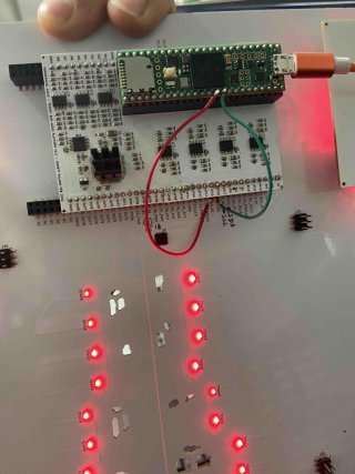
Also tried jumpering the SCL and SDA pins directly from T4 to the PCB just to make sure the headers weren't the issue. Still the same results:

T4_Jumpered.jpg

Also found out how to upload photos haha, they just have to be real small... :cool:
 
I'm guessing U5 on the large bottom board is the IS31FL3236A chip?

Is Teensy 4.1 providing all the power to run everything? Or is another power supply involved somehow? Just trying to get an idea of what will be needed. Since this problem doesn't happen with any of the many I2C devices I have, there's no way I can do anything without getting the hardware needed to reproduce this problem.

For now it’s just powered via USB 5V. I’ve also tried providing 5V from an external supply but it doesn’t make a difference.
 
Actually looks like I figured it out by adding an additional coupling cap to the 5V line entering the IS31 IC. No longer getting I2C errors with the additional filtering present. Maybe worth noting however that T3.2 worked whether the coupling cap was present or not, whereas with T4 they need to be present &#55358;&#56596;
 
Back
Top