Hi everyone,
I have a two-part question here. I am working on a method to collect signal from a specified IMU and analyze it in tandem with various analog signals.
1.) Acquire data from a specific IMU, via I2C.
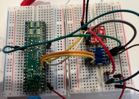
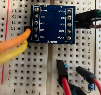
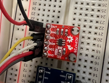
I have tried using both Arduino Uno and Teensy 4.1 to collect signal from a TDK ICM-42670-P 6-axis IMU (https://invensense.tdk.com/wp-content/uploads/2021/07/DS-000451-ICM-42670-P-v1.0.pdf) using a number of libraries from other sensors (MPU6050, MPU9050, ICM-20948, etc) to no avail; I usually either get arrays of ones that don't change when I move the accelerometer around, or I get a message expressing a failure to connect to the IMU. One of the codes I've used happens to be the full set of code from this thread: https://forum.pjrc.com/threads/61755-TEENSY-4-0-reading-wrong-data-on-GY-521-MPU6050-Breakout-Board. I am providing 3.3V from the board with external 2.2k pull-up resistors to the IMU and DAC. I'm using Pins 18 and 19 for the SDA and SCL, respectively.
2.) Send such data back out to a DAC to sync with other analog signals.
I imagine this might be the easier part of this project, since there is a library associated with the MCP4275, which I'm using. One main concern I have is how to wire the signal coming in from the IMU, out through another pair of digital pins.
Here are images of my setup. I hope this clears things up. I'm sorry I don't have much code other than what's in the thread I've included (cred to the author for this one), but any type of foundation would help me tons with the coding. Thanks!


UPDATE: I used the code listed at the bottom of the thread in the link. Credit to @Droid!
Here's what I see so far in the serial monitor:
Calibrating Gyro
Gyro Calibration Complete
Calibrating Accelerometer
Accelerometer Calibration Complete
0.00 / -0.00
0.00 / -0.00
0.00 / -0.00
0.00 / -0.00
0.00 / -0.00
0.00 / -0.00
0.00 / -0.00
0.00 / -0.00
~.~~ / -~.~~ (repeating zeros)
Here's the output when I verify/upload:
I have a two-part question here. I am working on a method to collect signal from a specified IMU and analyze it in tandem with various analog signals.
1.) Acquire data from a specific IMU, via I2C.
I have tried using both Arduino Uno and Teensy 4.1 to collect signal from a TDK ICM-42670-P 6-axis IMU (https://invensense.tdk.com/wp-content/uploads/2021/07/DS-000451-ICM-42670-P-v1.0.pdf) using a number of libraries from other sensors (MPU6050, MPU9050, ICM-20948, etc) to no avail; I usually either get arrays of ones that don't change when I move the accelerometer around, or I get a message expressing a failure to connect to the IMU. One of the codes I've used happens to be the full set of code from this thread: https://forum.pjrc.com/threads/61755-TEENSY-4-0-reading-wrong-data-on-GY-521-MPU6050-Breakout-Board. I am providing 3.3V from the board with external 2.2k pull-up resistors to the IMU and DAC. I'm using Pins 18 and 19 for the SDA and SCL, respectively.
2.) Send such data back out to a DAC to sync with other analog signals.
I imagine this might be the easier part of this project, since there is a library associated with the MCP4275, which I'm using. One main concern I have is how to wire the signal coming in from the IMU, out through another pair of digital pins.
Here are images of my setup. I hope this clears things up. I'm sorry I don't have much code other than what's in the thread I've included (cred to the author for this one), but any type of foundation would help me tons with the coding. Thanks!


UPDATE: I used the code listed at the bottom of the thread in the link. Credit to @Droid!
Code:
#include <Arduino.h>
#include <Wire.h>

double gyro_x, gyro_y, gyro_z;
double gyro_x_error, gyro_y_error, gyro_z_error;
double gyro_x_sum, gyro_y_sum, gyro_z_sum;
unsigned long cycle_start;
double dT = .002;
double dPitch, dRoll;
double acc_x, acc_y, acc_z;
double acc_pitch, acc_roll, acc_magnitude;
double acc_pitch_error, acc_roll_error;
double pitch, roll;
double pitch_feedback_error, roll_feedback_error;
double desired_pitch, desired_roll;
double acc_magnitude_sum, acc_magnitude_initial;
double servo_roll, servo_pitch;
int average_cycle_count = 2000;

//FUNCTIONS

void setup_mpu_6050_registers(){
  Wire.beginTransmission(0x68);
  Wire.write(0x6B);
  Wire.write(0x00);
  Wire.endTransmission(true);
}

void read_mpu_6050_data(){
  Wire.beginTransmission(0x68);
  Wire.write(0x3B);
  Wire.endTransmission(false);
  Wire.requestFrom(0x68, 6, true);

  //Store accelerometer values and divide by 16384 as per the datasheet
  acc_x = (int16_t)(Wire.read() << 8 | Wire.read()) / 16384.0;
  acc_y = (int16_t)(Wire.read() << 8 | Wire.read()) / 16384.0;
  acc_z = (int16_t)(Wire.read() << 8 | Wire.read()) / 16384.0;
  acc_magnitude = sqrt(acc_x * acc_x + acc_y * acc_y + acc_z * acc_z);

  Wire.beginTransmission(0x68);
  Wire.write(0x43);
  Wire.endTransmission(false);
  Wire.requestFrom(0x68, 6, true);

  //Store gyroscope values and divide by 131.0 as per the datasheet to convert to degrees/sec
  gyro_x = (int16_t)(Wire.read() << 8 | Wire.read()) / 131.0 - gyro_x_error;
  gyro_y = (int16_t)(Wire.read() << 8 | Wire.read()) / 131.0 - gyro_y_error;
  gyro_z = (int16_t)(Wire.read() << 8 | Wire.read()) / 131.0 - gyro_z_error;
}

//Calculate the average initial gyroscope values to find the error
//Supposed to be 0 deg/sec because it is initially at rest
//This allows us to eliminate drift along the roll and pitch axes
void calculate_gyro_error(){
    for (int cal_int = 0; cal_int < average_cycle_count; cal_int++){ //average_cycle_count cycles
    read_mpu_6050_data(); //Retrieve gyro data
    gyro_x_sum += gyro_x; //sum the values
    gyro_y_sum += gyro_y;
    gyro_z_sum += gyro_z;

    delay(2);
  }

  gyro_x_error = gyro_x_sum / average_cycle_count; //divide by average_cycle_count to get average deg/sec
  gyro_y_error = gyro_y_sum / average_cycle_count;
  gyro_z_error = gyro_z_sum / average_cycle_count;
}

//Calculate the average initial accelerometer pitch and roll values
//This will be the error since we take the startup position to be 0 on the pitch and roll axes
void calculuate_accelerometer_error(){

  for (int cal_acc_int = 0; cal_acc_int < average_cycle_count; cal_acc_int++){

    read_mpu_6050_data(); //get the accelerometer data

    acc_pitch_error += (atan(acc_y / sqrt(pow(acc_z, 2) + pow(acc_x, 2))) * 180 / PI); //sum the accelerometer pitch and roll angles in degrees
    acc_roll_error += (atan(-1 * acc_z / sqrt(pow(acc_y, 2) + pow(acc_x, 2))) * 180 / PI);
    acc_magnitude_sum += acc_magnitude;

    delay(2);
  }

  acc_pitch_error /= average_cycle_count; //divide by average_cycle_count to get the average pitch and roll values
  acc_roll_error /= average_cycle_count;
  acc_magnitude_initial = acc_magnitude_sum / average_cycle_count;

}

//Calculuate pitch and roll values
void calculate_pitch_roll(){
  dPitch = gyro_z * dT; //small change in angle for each cycle
  dRoll = gyro_y * dT;

  //Accelerometer-based calculations
  acc_pitch = (atan(acc_y / sqrt(pow(acc_z, 2) + pow(acc_x, 2))) * 180 / PI) - acc_pitch_error; //calculate pitch and roll values according to accelerometer and subtract the error
  acc_roll = (atan(-1 * acc_z / sqrt(pow(acc_y, 2) + pow(acc_x, 2))) * 180 / PI) - acc_roll_error;

  //Calculating the final pitch and roll values
  if(abs(acc_magnitude - acc_magnitude_initial) <= .01){
    pitch = (pitch + dPitch) *.97 + acc_pitch * .03; //adding the small change in pitch and roll
    roll = (roll + dRoll) * .97 + acc_roll * .03; //gyro values are more precise but accel helps to eliminate drift
  }
  else{
    pitch = (pitch + dPitch);
    roll = (roll + dRoll);
  }


}

//MAIN
void setup() {

  Wire.begin();
  Serial.begin(9600);

  delay(100);

  setup_mpu_6050_registers(); //setup the registers

  Serial.println("Calibrating Gyro");

  calculate_gyro_error(); //get the gyroscope error values

  Serial.println("Gyro Calibration Complete");
  Serial.println("Calibrating Accelerometer");

  calculuate_accelerometer_error(); //get the accelerometer error values

  Serial.println("Accelerometer Calibration Complete");

}

void loop() {

  cycle_start = micros(); //start of cycle
  read_mpu_6050_data(); //get data from MPU6050
  calculate_pitch_roll(); //calculate pitch and roll from MPU6050

  Serial.print(pitch);
  Serial.print(" / ");
  Serial.println(roll);


  while(((micros() - cycle_start) / 1000000.0) < dT);
}
Here's what I see so far in the serial monitor:
Calibrating Gyro
Gyro Calibration Complete
Calibrating Accelerometer
Accelerometer Calibration Complete
0.00 / -0.00
0.00 / -0.00
0.00 / -0.00
0.00 / -0.00
0.00 / -0.00
0.00 / -0.00
0.00 / -0.00
0.00 / -0.00
~.~~ / -~.~~ (repeating zeros)
Here's the output when I verify/upload:
Code:
I2C_Read_Teensy: In function 'void read_mpu_6050_data()':
C:\Users\MindMics User\Documents\Arduino\I2C_Read_Teensy\I2C_Read_Teensy.ino:33:33: warning: ISO C++ says that these are ambiguous, even though the worst conversion for the first is better than the worst conversion for the second:
   Wire.requestFrom(0x68, 6, true);
                                 ^
In file included from C:\Program Files (x86)\Arduino\hardware\teensy\avr\libraries\Wire/Wire.h:26:0,
                 from C:\Users\MindMics User\Documents\Arduino\I2C_Read_Teensy\I2C_Read_Teensy.ino:2:
C:\Program Files (x86)\Arduino\hardware\teensy\avr\libraries\Wire/WireIMXRT.h:97:10: note: candidate 1: uint8_t TwoWire::requestFrom(int, int, int)
  uint8_t requestFrom(int address, int quantity, int sendStop) {
          ^
C:\Program Files (x86)\Arduino\hardware\teensy\avr\libraries\Wire/WireIMXRT.h:91:10: note: candidate 2: uint8_t TwoWire::requestFrom(uint8_t, uint8_t, bool)
  uint8_t requestFrom(uint8_t address, uint8_t quantity, bool sendStop) {
          ^
C:\Users\MindMics User\Documents\Arduino\I2C_Read_Teensy\I2C_Read_Teensy.ino:44:33: warning: ISO C++ says that these are ambiguous, even though the worst conversion for the first is better than the worst conversion for the second:
   Wire.requestFrom(0x68, 6, true);
                                 ^
In file included from C:\Program Files (x86)\Arduino\hardware\teensy\avr\libraries\Wire/Wire.h:26:0,
                 from C:\Users\MindMics User\Documents\Arduino\I2C_Read_Teensy\I2C_Read_Teensy.ino:2:
C:\Program Files (x86)\Arduino\hardware\teensy\avr\libraries\Wire/WireIMXRT.h:97:10: note: candidate 1: uint8_t TwoWire::requestFrom(int, int, int)
  uint8_t requestFrom(int address, int quantity, int sendStop) {
          ^
C:\Program Files (x86)\Arduino\hardware\teensy\avr\libraries\Wire/WireIMXRT.h:91:10: note: candidate 2: uint8_t TwoWire::requestFrom(uint8_t, uint8_t, bool)
  uint8_t requestFrom(uint8_t address, uint8_t quantity, bool sendStop) {
          ^
Memory Usage on Teensy 4.1:
  FLASH: code:15708, data:5244, headers:8740   free for files:8096772
   RAM1: variables:5728, code:12832, padding:19936   free for local variables:485792
   RAM2: variables:12384  free for malloc/new:511904
Last edited:

