Sparkfun Tlc5940 and Teensy 4.0

seblanc

Member
Hi all,
I'm using the Teensy 4.0 with the TLC5940 module from Sparkfun, and the LEDs are not set correctly. With the following code, which lights up sequentially the 16 LEDs, the intensity varies from one LED to the other (even lighting up the next one sometimes).

Code:
#include <Arduino.h>
#include "Tlc5940.h"

void setup()
{
  Tlc.init(0);
}

void loop()
{
  while(1) {
    for (int i=0; i<16; i++) {
      Tlc.clear();
      delay(100);
      Tlc.set(i, 128);
      delay(100);
      Tlc.update();
      delay(500); 
    }
  }
}

I assume there are timing issues, as everything works like a charm with a Teensy 3.2. I've tested several Sparkfun module and Teensy 4.0.

Any idea where it could come from?
 
Might help to know where your tlc5940 library is coming from and in particular which version of Teensyduino you have installed.

I know it is one of @PaulStoffregen libraries, that are installed by Teensyduino.

But I see he did a commit back in February to support T4.
And in July bumped the version to .16.

So you may want to make sure you are running his latest code. And if you are running the currently released Teensyduino, you may want
to doublecheck that you don't have a different version in your <sketches>/library folder
 
Hi KurtE,
Indeed, I was missing few information. I use PlatformIO, and here are the versions in use:
- Teensyduino 1.54
- Tlc5940 (from @PaulStoffregen) 0.15

I will update all that and let you know if it solves the problem
 
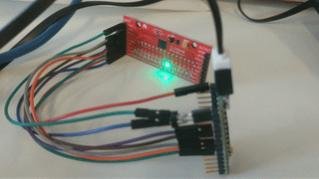
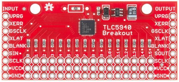
Is this the Sparkfun TLC5940 board you're using?

tlc5940.jpg

I'm trying to follow which wires connect to which pins and compare with the Tlc5940 library docs, but it's difficult with such a small photo. Still, I see a green wire on Teensy's GND pin. Looks like it goes to VPRG. Just below I see a blue wire which looks like it connects to Teensy pin 0. It seems to go to GND on the TLC5940. Maybe these 2 wires are shorted together? Difficult to see.
 
Also, I see you have <Arduino.h> include... so quick question, are you using Arduino with Teensyduino, or PlatformIO?

If PlatformIO, please at least give this a try with Arduino 1.8.19 with Teensyduino 1.57. That is the only software combination that's actually been tested and know to work.
 
Hi @stereodan and @PaulStoffregen,
My appologize for the silence. I'm coming back to this unresolved issue.
I've redo the tests (same code as above), using Teensy 3.2, all is fine, using Teensy 4.0 doesn't.

Here's what I tested:
IDE: VSCode + PlatformIO
Platform: Teensy 4.17.0 (Teensyduino v1.57 according to the changelog)
Library: 0.15 (doesn't work), 0.16 (doesn't work) freshly downloaded from https://github.com/PaulStoffregen/Tlc5940

IDE: Arduino IDE 2.0.4
Board: Teensy 1.58
Library: Tlc5940 0.16

Same issue persist: the LEDs are turned on and off in sequence (as described in the code above) but with random intensities, as if the communication is too fast (the Tlc5940 misses some bits).

Here's a diagram of how I connect the Teensy 3.2 and 4.0 (according to the guidelines described here: https://www.pjrc.com/teensy/td_libs_Tlc5940.html)


Any help/suggestion is appreciated! My next step is to analyse the signals on the scope and compare Teensy 3.2/4.0.
 
I have had bad experiences with this breakout board. Almost immediately after using it it became defective. Your problem sounds a lot like a bad connection, but maybe on the Teeny side since it works well with T3.2.

Very mysterious but certainly a hardware configuration issue.
 
Thanks for your feedback @stereodan!
We've done a custom board with 3 chained Tlc5940, and it doesn't work either with the Teensy 4.0, although it works like a charm with the Teensy 3.2. I'm not sure the Sparkfun board is to blame here unfortunately.
 
This is very odd, because I too have designed a custom board for up to 16 chained TLC5940 with the T4.0, I've constructed this board twice with up to 8 chips populated and it works great.

I assume if you are using T3.2 and T4.0 on the same board you are making some modifications to move the pins around to match, obviously making 5 connections isn't too complicated so this is pointing to a software issue. Still, if you want to send me your board design I can check it.

I've used the Arduino IDE and Visual Micro. Maybe PlatformIO is the problem? Since that seems to be the only difference here.

The random intensities, is a problem I've experienced twice, once was a bad connection of the serial line and the other was when I was trying to double the frequency of the timers running the chip.
 
We've done a custom board with 3 chained Tlc5940, and it doesn't work either with the Teensy 4.0, although it works like a charm with the Teensy 3.2.

Completely blind guess, maybe it's a high speed signal quality issue? Teensy 4.0 has much higher bandwidth on its digital outputs.

We saw this with MCLK on the audio shield, where STGL5000 works fine with Teensy 3.2 even with several inches of wire, but fails with Teensy 4.0 unless a resistor is placed in series with the MCLK signal to limit the extremely high speed overshoot / undershoot, even with the audio shield directly above connected through only header pins and the PCB traces. Then in hindsight, we discovered Teensy 3.6 also fails with several inches of wire, but works with very short wires or only header pins between the 2 boards. So Teensy 3.6 is somewhere between Teensy 3.2 and 4.0 in terms of high speed signal bandwidth issues. Point is, we never knew STGL5000 was so sensitive (it's certainly not mentioned in NXP's datasheet or any other documentation) until we had practical experience (eg: "why doesn't this work when the signals are correct") with Teensy 4.0 beta test boards.

During the Teensy 4.0 beta testing, the audio shield went from Rev B to Rev C, just to add a 100 ohm resistor on MCLK for better compatibility with Teensy 3.6 and to allow it to work with Teensy 4.0 using wires. Of course Rev D and D2 have since been made with the Teensy 4.0 and that same 100 ohm resistor. You can see it on the audio shield schematics.

https://www.pjrc.com/store/teensy3_audio.html

So for a completely blind shot in the dark, try adding 100 ohm resistors between the Teensy 4.0 pins and connecting wires. I'd start with GSCLK, then try SCLK and DIN. If more convenient, fine to add the resistor close to the TLC5940 chip rather than on the Teensy side. All that matters is it's somewhere in series with the wire, so the end result at the TLC5940 pin isn't overshoot / undershoot / ringing / reflections which can happen with very high bandwidth signals travel along a length of wire.

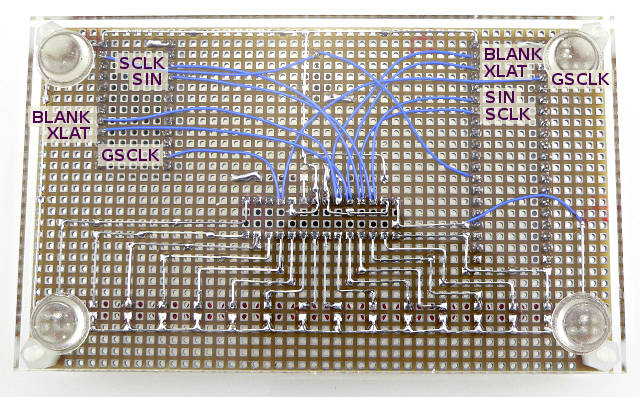
I did test Teensy 4.0 and TLC5940, but only on the board you can see on the Tlc5940 Library page. It had relatively short wires and the top side is a ground plane. That's probably much better for high speed signal quality than the longer wires in the photo on msg #4. Maybe the TLC5940 chip is sensitive to this problem, perhaps like STGL5000 with Teensy 3.6 where it works with short wires, so we just haven't really built up the practical wiring length experience yet?

td_libs_Tlc5940_2.jpg

(this photo is from before some extra socket and wires were added to test Teensy 3.2 and 4.0, but it can give an idea of the approx wire lengths used)
 
Last edited:
Actually, this sounds possible, I remember now having some similar issues while breadboarding with the TLC5940 using longer jumpers. Worth a shot.
 
Having multiple TLC5940 chained together with lengthy wires will tend to aggravate any high speed signal quality problems.

I ordered only 2 from Sparkfun, just so I could check the chaining connection, but before I thought about our experience with MCLK on the audio shield. If this really is an issue, I want to develop the practical knowledge and update the Tlc5940 page. But I also have a ton of other work pending and I can't pour a lot of time into TLC5940. Really hoping to hear some feedback on whether adding resistors in series with the signals helps for the problems already seen.
 
A 100ohms resistor in serie at the output pin 7 (SCLK signal) of the Teensy 4.0 solves the problem! A big thanks PaulStoffregen.
I first tried on the GSCLK, but had no effect, then on SCLK.

For the sake of understanding, I measured the signals at the board side (with approx 120mm cable length between the Teensy and the SparkFun Tlc5940):

SCLK signals on the SparkFun Tlc5940 side:

Teensy 4.0, without 100ohms serie resistor:


Teensy 4.0, with 100ohms serie resistor:


Teensy 3.2 (no resistor):


Note: adding the resistor only on SCLK fixes the random illumination, however, I also measured overshoots for the following signals: SCLK, SIN, BLANK, XLAT, GSCLK. In future design, I will add resistors to all of these pins.
 
This is great. The current library runs the TLC at 4 MHz and when I tried to double the frequency I encountered this overshoot. I'll have to try adding the resistors!
 
I checked a few post and I see a lot of questiins when running more than a few tlc's. In my project I see when more than 6 tlc in serie problems. What is the rule when the buffer is needed? I think a lot of projects run into this
 
There is no hard 100% certain rule. Such a rule is impossible because the TLC5940 doesn't have specifications for overshoot or other issues. And even if it did have this info, any attempt at a rule would involve multiple factors that are very hard to estimate, like the actual bandwidth or rise time / fall time of the waveform and characteristic impedance and length of the wiring used.
 
Ok clear, so best will be to use for.ex. the hex inverters mentioned in a other post. Combined with a 100E res on the sclk. Especialy when using long wires going to boards. Ill post later on an example when stable, here im using 80cm wires. With a pic. From thr clk lfor reference for futere projects.
 
@Paul. I'm still trying to figure out a small rule of thumb, since I have now 20 boards from a project to source some date. Since I see that a lot of projects use wires up to 1m from the board untill the teensy. Twisting, shielding, separate power etc.ledstrip_resized.jpg
 
I'm still trying to figure out a small rule of thumb

For a rule of thumb, I would say "add a 100 ohm resistor between the Teensy pin and (lengthy) wire which connects to the TLC5940(s)". If connection directly to the Teensy pin isn't feasible, try to minimize the wire length between the Teensy pin and this resistor. But don't stress to much over a "short" wire, like 2 cm or 1 inch. If the lengthy wire running to the TLC5940(s) is on a 4+ layer PCB with ground plane, perhaps reduce the resistor to 68 or 47 ohms. If the wire is "loose" (not inside a cable where the ground remains physically close), perhaps increase the resistor to 120, 150 or even 220 ohms. But a cable where the signal wire and ground wire remain close is preferable. If using buffer chips to boost the signal before transmitting to TLC5940 chip(s), add the resistor close to the buffer's output pin, before it connects to the long wire.

Or short version: add a 100 ohm resistor in line with the signal.

How's that for a rule of thumb?
 
I'm lost now. I added a hex inv buffer 74HC14 to feed in the other buffers. But when I measure the output its worse than without an buffer. It seems the buffer cant handle it or am I overlooking something. the input to the buffers is oke but output is terrible. (this is only the cable not connected to tlc boards.)
For cable I used a utp cable 1meter. Can the spi speed be adjusted in de tlclib?

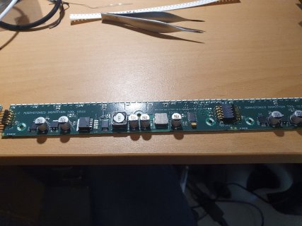
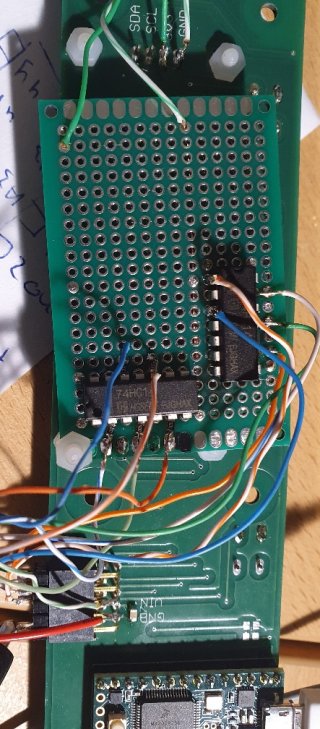
20230502_184324_resized.jpg
the buffers added

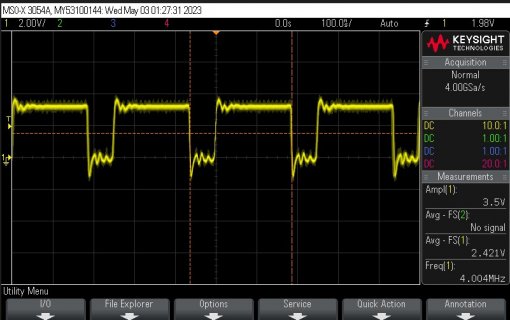
scope11.jpg
input from first hex inv.

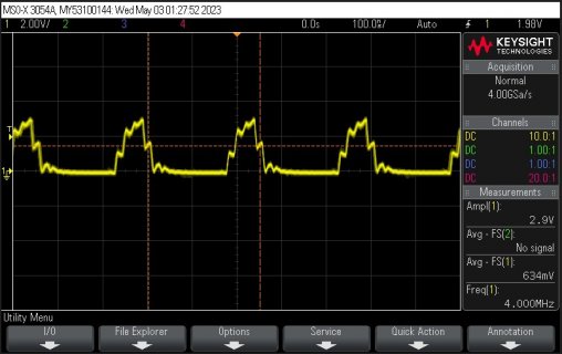
scope12.jpg
after the 100E res.
 
Back
Top