trying to make work a touchscreen on Teensy 4.1

Romano

Member
Hi all.

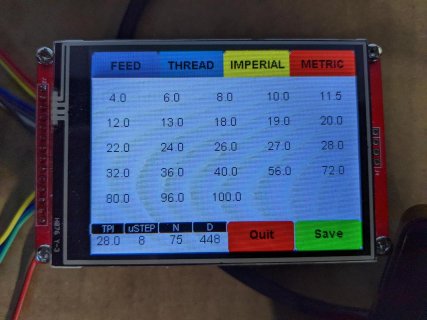
I'm getting crazy with this issue: I'm trying to work with a resistive TS (driven by a XTP2046) installed on a cheap TFT (ILI 9488, 480x320) but I' m loosing my mind since yesterday.
Yesterday I received the display, connected it and started to develop immediately, but when it came to use the TS i did not understand which pins I've to connect.
I tried several different libraries, the first one was Paul's touchscreenXP2046 but I didn't understand where I have to connect MOSI, MISO and CLK (TDI, TDO and TCK on my display connector).
I assume that I have to connect a separate and unique CS pin for the touchscreen on TEENSY 4.1 (and I've chosen the pin 0 for TS and pin 21 for TFT), because the CS addresses each SPI peripheral using the respective channel, but AFAIK ILI9488 does not allow to share its MISO, MOSI and TCK with any other device as it does not allow 3state pins

I've chosen (and reserved) the following pins for TS on the Teensy4.1 board:
CS1: 0
MISO1 1
MOSI1 26
SCK(TCK) 27
IRQ(PEN) 28

I cannot freely choose the pins on Teensy, as I'm already using two MPU6050s, a voice/audio board (WT588D), a bluetooth (serial) device and a high speed ADC (2 channels, 100MHz, that requires 10 parallel bits/pins for each channel)
...is it possible to get a library that allows the developer to freely choose the SPI pins for the touchscreen?

ps. I tried to share MISO, MOSI and SCK with the TFT too, but it didn't work of course.

besides I'm using the following pins for the TFT:
CS: 10
MOSI: 11
MISO: 12
SCK: 13
RST 23 (I connected it using a 4.7K resistor to the pin 23 and pulled it always high in my sketch)

it got it work flawlessly in less than 5 minutes.

If I get the TS work on an example program, I can study its behavior on the example and then develop the sketches of my project.

thank you :)

Romano
 
Hi all.

I'm getting crazy with this issue: I'm trying to work with a resistive TS (driven by a XTP2046) installed on a cheap TFT (ILI 9488, 480x320) but I' m loosing my mind since yesterday.
Yesterday I received the display, connected it and started to develop immediately, but when it came to use the TS i did not understand which pins I've to connect.
I tried several different libraries, the first one was Paul's touchscreenXP2046 but I didn't understand where I have to connect MOSI, MISO and CLK (TDI, TDO and TCK on my display connector).
I assume that I have to connect a separate and unique CS pin for the touchscreen on TEENSY 4.1 (and I've chosen the pin 0 for TS and pin 21 for TFT), because the CS addresses each SPI peripheral using the respective channel, but AFAIK ILI9488 does not allow to share its MISO, MOSI and TCK with any other device as it does not allow 3state pins

I've chosen (and reserved) the following pins for TS on the Teensy4.1 board:
CS1: 0
MISO1 1
MOSI1 26
SCK(TCK) 27
IRQ(PEN) 28

I cannot freely choose the pins on Teensy, as I'm already using two MPU6050s, a voice/audio board (WT588D), a bluetooth (serial) device and a high speed ADC (2 channels, 100MHz, that requires 10 parallel bits/pins for each channel)
...is it possible to get a library that allows the developer to freely choose the SPI pins for the touchscreen?

The SPI pins are tied to the underlying microprocessor. The only user pin that you can change is using pin #39 for MISO1 instead of pin #1. In general, you should be able to use any pin for CS1 instead of pin #0.

I can think of some possible solutions, which each has their own issues:
  • Use something that fits in the SD card slot to allow you to access pins 42 for MISO2, pin 43 for MOSI2, pin 45 for SCLK2, possibly pin 44 for CS2 (for example https://www.sparkfun.com/products/9419).
  • Don't use the flash/psram pads underneath the Teensy 4.1 and solder wires to pin 54 for MISO2, pin 50 for MOSI2, and pin 49 for SCLK2.
  • Write your own SPI support (so-called bit-banging). It is much slower than using hardware SPI, but it may be fast enough to track human responses.
  • I don't know if it is possible, but possibly adding something to make the pins tri-state.
  • Add a small microprocessor that can do SPI, and then connects to the Teensy using some other protocol (uart, i2c, etc.) to relay what the touch screen records.
  • I dimly remember there used to be touch screens that used two analog inputs instead of SPI, but I don't remember the details.
 
For a standard ILI9341 (PJRC version) I use the following
Code:
#define TFT_DC  9
#define TFT_CS 10
#define TFT_RST -1
#define TFT_SCK 13
#define TFT_MISO 12
#define TFT_MOSI 11
#define TOUCH_CS  8
Which works for me.
PXL_20220901_221209275_1920.jpg

I'd like a larger display, myself, but need to develop my application on this display first. For the PJRC display it is recommended to drive TFT_RST with +5V through a 100 ohm resistor.
 
The SPI pins are tied to the underlying microprocessor. The only user pin that you can change is using pin #39 for MISO1 instead of pin #1. In general, you should be able to use any pin for CS1 instead of pin #0.

I can think of some possible solutions, which each has their own issues:
  • Use something that fits in the SD card slot to allow you to access pins 42 for MISO2, pin 43 for MOSI2, pin 45 for SCLK2, possibly pin 44 for CS2 (for example https://www.sparkfun.com/products/9419).
  • Don't use the flash/psram pads underneath the Teensy 4.1 and solder wires to pin 54 for MISO2, pin 50 for MOSI2, and pin 49 for SCLK2.
  • Write your own SPI support (so-called bit-banging). It is much slower than using hardware SPI, but it may be fast enough to track human responses.
  • I don't know if it is possible, but possibly adding something to make the pins tri-state.
  • Add a small microprocessor that can do SPI, and then connects to the Teensy using some other protocol (uart, i2c, etc.) to relay what the touch screen records.
  • I dimly remember there used to be touch screens that used two analog inputs instead of SPI, but I don't remember the details.


Hi Michael, thank you very much! :)
I used the SPI port 1 of the Teensy 4.1, if you see the board diagram, the configuration I used is exactly the configuration of the port SPI 1 on Teensy 4.1 board (CS1 is on the 0 pin)
I already soldered both PSRAM and FLASH on the corresponding pads under the board, as I need much more RAM than 1 MB (more than 4) and more space for non volatile data to be kept

I already programmed the protocol of the WT588D as I didn't find anything, when I decided to connect it to the board (I have some 6...7 of them in the closet and I wanted to "solve" within the afternoon).
I looked for a while on the net, didn't find anything immediately, and decided to develop it by myself (less than 30 C lines in total)
As you very probably know, developing a custom SPI protocol requires optimization in general, in fact I discovered that the time required to wait until the WT588D BUSY signal is on is more than 20milliseconds, as described in the datasheet.
It's around 28millisecs, but before to discover this difference and write "30" in the appropriate field I fought with that board for more than 2 hours... and I discovered it just because I connected the state analyzer to the busy pin.>

In any case I'd try to follow other solutions instead to exclude the usage of the SD card, as the display board has a 40 pins connector on the back that allows to control the TFT with the a 16 bits parallel port + the appropriate 4 pins that transmit the X,Y touch coordinates. I was just thinking to get an immediate solution.
I bought this board:

https://it.aliexpress.com/item/1005..._list.0.0.10b23696pdxuCP&gatewayAdapt=glo2ita

thank you again
Romano
 
Thank you very much Clinker, after a strong coffee I'l try to study that way.

May you post the code of an example, using those pins?

concerning the RST I connected it to the pin 23 with a 4.7K resistor, I didn't read anything about it on the net, but thought that in any case the impedance of that pin on the TFT board was very probably high, and in fact it works perfectly! :)


Romano
 
Sorry,

Sometimes it might help to understand if we get back to basic questions to understand:

Which display are you using?
I have played with a few. Most of them have looked like:
https://www.ebay.com/itm/3-5-inch-4...le-Display-Color-Screen-ILI9488-/175099011145

I believe you can get these with or without touch...

Also, I am trying to remember if these have issues with the MISO pin on the display. That is that they don't play well with other SPI devices? Been awhile since I played with one.
If it is an issue, you can either do something like use a buffer chip with it or if you are not trying to do reads from it simply not connect it.

What code are you running?

If you have both the display and the Touch on same SPI buss and don't have external Pull up resistors on the two Chip Select pins (the display and touch),

Then I would typically in setup do: something like:
Code:
pinMode(CS_TFT, OUTPUT);
digitalWriteFast(CS_TFT, HIGH);
pinMode(CS_TOUCH, OUTPUT);
digitalWriteFast(CS_TOUCH, 

// (now do the setup/init methods for the display and tft)
Again, it might help if you posted a small sketch that shows what you are doing and what is not working. That way some of us may go into our spare parts(display) bin/box and pulll one out and
see what it is doing.

Edit: Should mention there have been a few threads on this display and like including:
https://forum.pjrc.com/threads/55735-ILI9488_t3-Support-for-the-ILI9488-on-T3-x-and-beyon
 
Here's something I did to test a digital read out head. (DRO for machine tool positioning.) It also works for rotary encoders. This uses luni's EncoderTool, which I highly recommend.

Code:
#include <EncoderTool.h>
#include <ILI9341_t3n.h>
#include <ili9341_t3n_font_Arial.h>
#include <ili9341_t3n_font_ArialBold.h>
#define thisGREY 0x3A07
#define TFT_DC  9
#define TFT_CS 10
#define TFT_RST -1
#define TFT_SCK 13
#define TFT_MISO 12
#define TFT_MOSI 11

using namespace EncoderTool;

Encoder DROZ_Enc;

ILI9341_t3n tft = ILI9341_t3n(TFT_CS, TFT_DC, TFT_RST, TFT_MOSI, TFT_SCK, TFT_MISO);

int errorcount, myacc;
float conversionfactor;
volatile float Zval, oldZval;
uint16_t cxg, cyg;

void onDROZ_Changed( int value, int delta )
{
  if (delta >0)
  {
    if (delta>1)
    {
      Serial.printf("Fault!  delta =% i\n", delta);
      errorcount+= 1;
    }
    else
    {
      myacc = myacc + delta;
    }
    oldZval = Zval;
    Zval = myacc * conversionfactor;
  }
  if (delta<0)
  {
    if (delta<-1)
    {
      Serial.printf("Fault!  delta = %i\n", delta);
      errorcount += 1;
    }
    else
    {
      myacc = myacc + delta;
    }
    oldZval = Zval;
    Zval = myacc * conversionfactor;
  }
}

bool initMyDisplay(int rotation)
{
  tft.begin();
  tft.setRotation(rotation);
  tft.fillScreen(ILI9341_BLACK);
  return true;
}

void mainMenu()
{
  tft.fillScreen(thisGREY);
  tft.setCursor(0,0);
  tft.setTextColor(ILI9341_WHITE);
  tft.setTextDatum(TL_DATUM);
  tft.setFont(Arial_18);
  tft.drawString("Digital Read Out V0.00", 0,0);
  tft.println();
  uint16_t cx = tft.getCursorX();
  uint16_t cy = tft.getCursorY();
  tft.setTextColor(ILI9341_GREEN);
  tft.drawString("Z axis", cx, cy);
  tft.println();
  cx = tft.getCursorX();
  cy = tft.getCursorY();
  cxg = cx;
  cyg = cy;
  tft.drawFloat(Zval, 4, cx, cy);
}

void setup() {
  // put your setup code here, to run once:
  while(!Serial && millis() < 4000);
  for(int i=5; i<8; i++) pinMode(i, OUTPUT);  // init these pins to outputs

  DROZ_Enc.begin(0,1, CountMode::full);  // A input pin0, B input pin1.  These are the quadrature encoder inputs to Teensy4.1
  DROZ_Enc.attachCallback(nullptr);
  DROZ_Enc.setValue(0);

  myacc = 0;
  errorcount = 0;
  conversionfactor = 1.0/5080.00;  // typical value for mag tape DRO's
  oldZval = 0.0;
  Zval = 0.0;

  if (!initMyDisplay(3))
  {
    Serial.println("Display failed to initialize");
    while(1);
  }
  mainMenu();
  DROZ_Enc.attachCallback(onDROZ_Changed);  // enable callback
}

void loop() {
  // put your main code here, to run repeatedly:
  
  if (Zval != oldZval)
  {
    // if count changed, update the display
    uint16_t x1, y1, w, h;
    oldZval = Zval;
    String newstr = "XXXXXXXX";
    tft.getTextBounds(newstr, cxg, cyg, &x1, &y1, &w, &h);
    tft.fillRect(x1, y1, w, h, thisGREY);
    tft.drawFloat( Zval, 4, cxg, cyg );
    //Serial.printf("Zval = %+7f4\n", Zval);
  } 
  delay(10);

}
This is with SPI0. I would imagine that it could be ported to SPI1 by simply changing the defines, but I have not tried it.
If you touch 0 or 1 with a logic high or low the readout value will change.
 
Sorry,

Sometimes it might help to understand if we get back to basic questions to understand:

Which display are you using?
I have played with a few. Most of them have looked like:
https://www.ebay.com/itm/3-5-inch-4...le-Display-Color-Screen-ILI9488-/175099011145

I believe you can get these with or without touch...

Also, I am trying to remember if these have issues with the MISO pin on the display. That is that they don't play well with other SPI devices? Been awhile since I played with one.
If it is an issue, you can either do something like use a buffer chip with it or if you are not trying to do reads from it simply not connect it.

What code are you running?

If you have both the display and the Touch on same SPI buss and don't have external Pull up resistors on the two Chip Select pins (the display and touch),

Then I would typically in setup do: something like:
Code:
pinMode(CS_TFT, OUTPUT);
digitalWriteFast(CS_TFT, HIGH);
pinMode(CS_TOUCH, OUTPUT);
digitalWriteFast(CS_TOUCH, 

// (now do the setup/init methods for the display and tft)
Again, it might help if you posted a small sketch that shows what you are doing and what is not working. That way some of us may go into our spare parts(display) bin/box and pulll one out and
see what it is doing.

Edit: Should mention there have been a few threads on this display and like including:
https://forum.pjrc.com/threads/55735-ILI9488_t3-Support-for-the-ILI9488-on-T3-x-and-beyon


Hi Kurt, thank you very much for your answer.

The display I'm trying to use, as I mentioned above, is this one:
https://www.aliexpress.com/item/325...st.0.0.10b23696pdxuCP&gatewayAdapt=4itemAdapt

ILI9488 + XP2046.


I'm using the ILI9488, that doesn't allow the three state, so I've chosen two different SPI for TFT and TS, in my first post I described the whole configuration.
I pulled the TFT CS (pin 10) with a 47K resistor, but I'm realizing right now that I did not connect any resistor between pin 0 (CS1 on teensy 4.1, used by the TS) and ground... so I'm doing it right now.
Assuming that there would be an example that let me choose which SPI port to use on Teensy 4.1, why I've never seen anything about the IRQ pin?

The fact is that I've read (more than once) "specify the CS pin, the others will be configured automatically". If it is so, is my configuration correct?

I referred to the pinout schematics that appears on the pjrc Teensy 4.1 mainpage, so I made the following connections, as described in the first post:

I've chosen (and reserved) the following pins for TS on the Teensy4.1 board:
CS1: 0
MISO1 1
MOSI1 26
SCK(TCK) 27
IRQ(PEN) 28

I cannot freely choose the pins on Teensy, as I'm already using two MPU6050s, a voice/audio board (WT588D), a bluetooth (serial) device and a high speed ADC (2 channels, 100MHz, that requires 10 parallel bits/pins for each channel)
...is it possible to get a library that allows the developer to freely choose the SPI pins for the touchscreen?

ps. I tried to share MISO, MOSI and SCK with the TFT too, but it didn't work of course.

besides I'm using the following pins for the TFT:
CS: 10
MOSI: 11
MISO: 12
SCK: 13
RST 23 (I connected it using a 4.7K resistor to the pin 23 and pulled it always high in my sketch)


I'd avoid the usage of another IC on my project, if possible. all in all I've 5 pins dedicated for the TS, and the whole architecture already involves several more important devices. In case I'd throw this TFT/TS out and choose another one.
The question is: is it really possible that I cannot connect a stupid TS to a teensy 4.1 using its complete and dedicated SPI1 port?

Ok, i'll take another look to your library. yesterday it was one of the tries I did, but maybe I forgot something.
Romano
 
Last edited:
thank you Clinker. Your code mainly manages the TFT, and my ILI9488 works flawlessly.
I'm just facing problem with the touchscreen.

I've to add that I was really astonished about the speed reached by the teensy 4.1 managing the display via SPI.
It's amazing. I used several screens in the past, with Arduino and some boards completely drawn by me (I own the complete Atmel environment, STK600...JTAG...).
When I tried for the first time to upload a RGB565 480x320 picture using the Teensy board I jumped from the chair!

Romano
 
one of the (many) libraries/examples I tried to run was this one:

Code:
#include <XPT2046_Touchscreen.h>
// #include "C:\Users\User\Documents\Arduino\libraries\XPT2046_Touchscreen-master"


#define CS_PIN  0
XPT2046_Touchscreen ts(CS_PIN);

 uint16_t x, y;
 uint8_t  z;

      TS_Point p = ts.getPoint();

void setup() {
  // put your setup code here, to run once:

      ts.begin();
      ts.setRotation(1);  

}

void loop() {

      if (ts.touched()) {
          ts.readData(&x, &y, &z); 

          Serial.print("x = ");
          Serial.print(p.x);
          Serial.print(", y = ");
          Serial.println(p.y);   
      }

}

Romano
 
thank you Clinker. Your code mainly manages the TFT, and my ILI9488 works flawlessly.
I'm just facing problem with the touchscreen.

I've to add that I was really astonished about the speed reached by the teensy 4.1 managing the display via SPI.
It's amazing. I used several screens in the past, with Arduino and some boards completely drawn by me (I own the complete Atmel environment, STK600...JTAG...).
When I tried for the first time to upload a RGB565 480x320 picture using the Teensy board I jumped from the chair!

Romano

I do have a much larger body of code that does touch panel stuff. I was looking for a small example and wasn't sure what the issue was. Here is part of stub of code to process touch.
Code:
void processTouch() {
  if (ts.touched()) {
    TS_Point p = ts.getPoint();
    // this maps the touched point to a pixel reference system
    uint16_t px = map(p.x, TS_MINY, TS_MAXY, 0, tft.width());
    p.y = map(p.y, TS_MINX, TS_MAXX, 0, tft.height());
    p.x = px;
    //Serial.printf("Point touched is: p.x = %i, p.y = %i\n", p.x, p.y);
    uint16_t x, y, w, h, nudge = 0;
    switch (menu) { // go thru the menu choices
      case 0: {
        x=1; y=199; w=80, h=40;
        if ((p.y > y)&&(p.y< y+h) && (p.x>x)&&(p.x<x+w))
          setup0touched = true;  // we go to setup mode
        w=80; h=40; x=tft.width()-2*w-1; y=199; 
        if ((p.y > y)&&(p.y< y+h) && (p.x>x)&&(p.x<x+w))
            start0touched = true;  // we go to start mode
        w=80; h=40; x=tft.width()-w-1; y=199;
        if ((p.y > y)&&(p.y< y+h) && (p.x>x)&&(p.x<x+w))
            stop0touched = true;  // we go to stop mode
        break;
      }
     case 1: {
     // ...
    break;
    }
    default: { break; }
}
I happen to use a touch panel rotation of 1, which is horizontal with the connector on the left. However, the display is rotated to 3. This is a quirk of this PJRC display and is documented. Then the touch points line up with the display.
 
yes, Clinker.

rotation of the screen is not a problem, of course. If I get a working example I'll do several tests and tries.

30 seconds ago I tried to pull the TS CS pin (0) to ground with a 47K resistor and loaded again this example, but it doesn't work at all: I obtain nothing than "Pressure 4095, x=0 y=0" on the serial port. Moving the finger all over the screen

Code:
#include <XPT2046_Touchscreen.h>
#include <SPI.h>

#define CS_PIN  0
// MOSI=11, MISO=12, SCK=13

//XPT2046_Touchscreen ts(CS_PIN);
#define TIRQ_PIN  28
//XPT2046_Touchscreen ts(CS_PIN);  // Param 2 - NULL - No interrupts
//XPT2046_Touchscreen ts(CS_PIN, 255);  // Param 2 - 255 - No interrupts
XPT2046_Touchscreen ts(CS_PIN, TIRQ_PIN);  // Param 2 - Touch IRQ Pin - interrupt enabled polling

void setup() {
  Serial.begin(38400);
  ts.begin();
  ts.setRotation(1);
  while (!Serial && (millis() <= 1000));
}

void loop() {
  if (ts.touched()) {
    TS_Point p = ts.getPoint();
    Serial.print("Pressure = ");
    Serial.print(p.z);
    Serial.print(", x = ");
    Serial.print(p.x);
    Serial.print(", y = ");
    Serial.print(p.y);
    delay(30);
    Serial.println();
  }
}

Romano
 
Are you still using the pins:
Code:
CS1: 0
MISO1 1
MOSI1 26
SCK(TCK) 27
IRQ(PEN) 28

If so, this is SPI1:

Have you tried:
Code:
#define CS_PIN  0
XPT2046_Touchscreen ts(CS_PIN);

 uint16_t x, y;
 uint8_t  z;

      TS_Point p = ts.getPoint();

void setup() {
  // put your setup code here, to run once:

      ts.begin([COLOR="#FF0000"]SPI1[/COLOR]);
      ts.setRotation(1);  

}

void loop() {

      if (ts.touched()) {
          ts.readData(&x, &y, &z); 

          Serial.print("x = ");
          Serial.print(p.x);
          Serial.print(", y = ");
          Serial.println(p.y);   
      }

}

To tell the library to use SPI1 instead of SPI?
 
Unless you really want to slow things down, you don't need to restrict Teensy to 38400 baud. You can comment that line out and Teensy will output data at a much faster rate.
My displays are currently tied up, so I can't connect things the way you have. Don't have any spares at the moment.

My comment, at least looking at the code is I am unsure how you are physically connecting the pins. Something seems inconsistent in your code.
Either you use (my working example)

TouchCS 8 could be anything
DC 9
CS 10
MOSI 11
MISO 12
SCLK 13

or you use
TouchCS1 ?
DC1 ?
CS1 0
MOSI1 26
MISO1 1
SCLK1 27

Point is, ts has to communicate over some bus. In my working example, it is over SPI0, ie. the upper set. Since you are using SPI1, you must use the lower set. I do know CS1, MOSI1 MISO1 and SCLK1 are special pins. Perhaps you could do a search on ILI9341 SPI1? Or ask a more detailed question for necessary and sufficient pins to operate on SPI1 with two hardware chip selects. It seems SPI0 has three possible hardware CS?

Seems the HW connections are not right. I had a problem when trying to use pin 32 as in input. It just plain didn't work. I changed the pin to 31, and it worked. In my case it was for DRO inputs. I wanted 29-32 for the inputs. Just didn't work. But 28-31 did work.
 
Unless you really want to slow things down, you don't need to restrict Teensy to 38400 baud. You can comment that line out and Teensy will output data at a much faster rate.

Note: Serial.begin(???); is optional, and for the most part the baud rate passed in is totally meaningless. that is, it makes no difference to the speed that the Teensy talks over USB. It always goes at USB speed.

Where the baud rate may be of some interest, is when for example you are using the Teensy as something like a USB to Serial adapter:
Like the Example sketch USBtoSerial. And it is more the other way around, in that we listen to what logical Baud rate the host is telling us to talk at.

In the example sketch it does code like:
Code:
  if (Serial.baud() != baud) {
    baud = Serial.baud();
      Serial1.begin(baud);
    }

Hope that makes sense.


Yes, I totally agree.

I just copied one of the several examples I downloaded from the internet.

That example is included in the PAUL's library found here:

https://github.com/PaulStoffregen/XPT2046_Touchscreen/blob/master/examples/TouchTest/TouchTest.ino

Since yesterday I tried to upload maybe 10 different libraries, in order to find one that let me set the pin I want (SPI1).
I just want to see the TS working, after that I will rewrite everything.

Romano
 
Last edited:
As I stated I used exactly that PIN configuration.

I checked it again right now, and it's absolutely correct.
Since yesterday I tried several libraries, because I'm trying to avoid to write a library for a touchscreen, the serial baudrate set to 38400 come from a Paul's example.
i just reported that example, since the fact that I'm trying several libraries until I find one that works correctly with the SPI1 port that I've chosen.

This is the example I copied and uploaded during the afternoon:

https://github.com/PaulStoffregen/XPT2046_Touchscreen/blob/master/examples/TouchTest/TouchTest.ino


Romano
 
Since yesterday I tried to upload maybe 10 different libraries, in order to find one that let me set the pin I want (SPI1).
I just want to see the TS working, after that I will rewrite everything.
.....
i just reported that example, since the fact that I'm trying several libraries until I find one that works correctly with the SPI1 port that I've chosen.

You need to use ts.begin(SPI1), as Kurt suggested in msg #13. Otherwise it will default to using the main SPI port, regardless of which pin you configure for CS.

I've updated the XPT2046_Touchscreen examples to show this, so hopefully this info will be easier to find in the future.

https://github.com/PaulStoffregen/X...mmit/cf3364816fd49c086b66fd7d0bb99fb270722155


SOLVED !

Thank you all and you in particular, Paul.

Ok, it was not a my fault, and of course you where all right.
The problem, I think, arises when somebody drinks half a gallon of Jack Daniels, and I think that it's exactly the case of somebody in China (ok... maybe Sake, but it doesn's change anything :D)

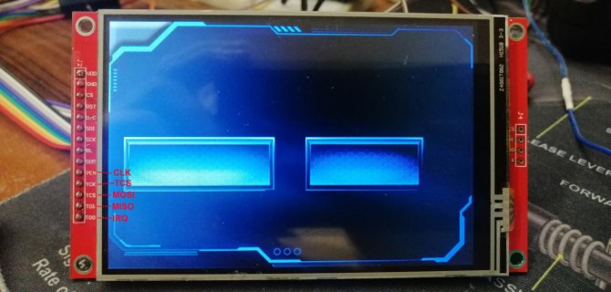
Look at the picture.

all in all it's some 40 years that I work in the software, firmware and hardware field. I was getting crazy and without any explanation.
Of course I need to specify to the library that Im' using the SPI1 instead of the SPI0, taking apart that I need to use (always!) 2 different CS pins. The CS pin addresses the device, but i didn't do anything wrong, and almost your suggestions where correct.

After got crazy, I attached my state analyzer (I always hate to do so because there is always alot of setup to do on my HP), all in all I'm using it since 1999, and it always solved the problem, when I called it into question.

Look at the picture. ALL THE PINS ARE WRONGLY NAMED. Of course it could never work.

it's working flawlessly, right now, but I was not able to make it work using the SPI1 port.
There is no way, at least with my Teensy and TFT/TS unit. If I connect all the pins to the SPI1, (CS on pin 0, the pin that immediately follows the ground), the following example does not work at all, if I connect 0 (CS), 1(MISO), 26(MOSI), 27(CLOCK), 28(IRQ).
I tried more than once, disconnecting everything too, and leaving just the TS connected to the SP1 port.

Code:
void setup() {
   
 ts.begin(SPI1); // use alternate SPI port
 ts.setRotation(1);
 while (!Serial && (millis() <= 1000));

}

the

and... guess?
I'm working with all the pins SHARED with the TFT. Despite the fact that the ILI9488 processor does not support 3 state.

I just connected the 0 PIN (CS1) to the TS and the 10PIN (CS0) to the TFT (IRQ is another thing, of course), but MISO, MOSI and CLK are respectively on the 12, 11 and 13 pins, TFT and TS, togheter.
All the 3 pins pulled with a 47K resistor (I don't think that it is needed at all, but it's one of my old habits).
This way is even better for me, since the fact that I set free 3 pins!

thank you again!

Romano

IMG_20220906_191923.jpg
 
Last edited:
Back
Top