Hi, All.
I have been working in a project that timing is critical. I have to implement the PSI5 protocol using teensy 4.1. The objective is to have four independent channels and the data for each channel must be updated through Ethernet.
About the PSI5 protocol:
1. It is a 189kbps protocol. So I am using a timer to run at 2.65us (Period of 5.3us).
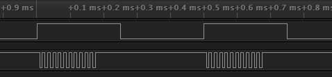
2. Each channel starts transmitting information after a sync pulse in the power line. After the sync pulse is detected using a falling edge in a pin, the timer is enabled. After 47us, the bit pattern is transmitted. 21 bits need to be transmitted after each sync pulse. After the bit transmission, the timer is turned off until the next sync pulse.
3. The PSI5 protocol is Manchester-enconded. So I am using two pins to generate the current modulation through an additional circuit.
What I have so far:
1. I am able to generate at the four channels the pattern that I want using one interrupt (Interval Timer or Periodic Timer). In this case, I can one have on sync pulse for synchronization for the four channels (not ideal, because each channels need to be independent). I am not using Ethernet at this part.
2. The next test was trying to make just two channels to work independently from each other. In this case, I tried to use two timers (Interval Timer or Periodic Timer). I have the expected pattern from two different sync pulses. However, I have a problem with timing for the two channels. When the second timer is enabled and the first one is already enabled (or the other way around). The two channels start to have a small delay/shifting at the pattern that is being transmitted. Even though, I establish different priorities I still get this undesirable behavior. The device that is reading this pattern does not accept any delays or small shifting in the transmitted bits.
3. The other test was running one channel with one timer. The signal is transmitted perfectly without any delays or shifting and the external equipment can read without any errors the PSI5 bit transmission for a timer running at 2.63us. However, when I enable the configuration of the Ethernet port using Native Ethernet (TCP/IP or UDP), the timer for the signal transmission starts to get a delay by the Ethernet port and the equipment starts to give errors saying that the signal is not respecting the timing. You can see on the oscilloscope that the Signal from time to time has a noticeable shifting. In this case, the Ethernet is not even sending or receiving bits from a external computer. It is just connected to the router. I am assuming here that the Ethernet is just checking status from time to time and this is messing with the timing for the timer I am using for signal generation.
Code:
// Set as global variables.
PeriodicTimer timers[4] = {PeriodicTimer(), PeriodicTimer(), PeriodicTimer(), PeriodicTimer()};
// This function is called when the raising edge of the Sync Pulse is detected. This function starts the timer for the bit generation
void ISR_Channel_0()
{
static int ch_idx = 0;
digitalWrite( channels[ch_idx].flipflopResetPin, HIGH);
if ( !channels[0].enabled )
{
timers[0].begin( generateSignalsCh0, channels[ch_idx].tp_div_2_us );
channels[ch_idx].counterPeriodGreater = 0, channels[ch_idx].outputCounter = -1;
channels[ch_idx].enabled = true, channels[ch_idx].newBitPattern = channels[ch_idx].confSetStop = false;
}
}
// This is the function for the signal generation. We have tried to reduce as much as we can. In one version for this function, we only had the digitalWrite to update the edges for the transmission. But when adding a second timer, we still had
// problems with one timer interfering with the other.
void generateSignalsTest ( uint8_t idx )
{
if ( channels[idx].enabled )
{
if ( !channels[idx].confSetStop)
{
channels[idx].initialized = channels[idx].confSetStop = true;
channels[idx].counterPeriodGreater = delayAfterPulse;
}
if ( channels[idx].initialized )
{
if ( channels[idx].counterPeriodGreater == 0x0 )
{
channels[idx].outputCounter++;
digitalWrite( channels[idx].outputPinA, CH0_bufferPatternDecoded[channels[idx].outputCounter] );
if ( channels[idx].outputCounter == 41 )
{
channels[idx].outputCounter = -1, channels[idx].counterPeriodGreater = 1;
channels[idx].endFrame = true;
}
}
else
{
channels[idx].counterPeriodGreater--;
if ( channels[idx].endFrame )
{
channels[idx].outputCounter = -1;
channels[idx].initialized = channels[idx].enabled = channels[idx].endFrame = false;
digitalWrite( channels[idx].flipflopResetPin, LOW);
timers[idx].stop();
}
}
}
}
}
In the setup I have:
for (int i = 0; i < 4; i++ )
{
ch_idx = i;
// Setting initial state for all channels' outputs: pins that drive the current modulation.
pinMode( channels[ch_idx].outputPinA, OUTPUT ), digitalWrite( channels[ch_idx].outputPinA, HIGH);
pinMode( channels[ch_idx].outputPinB, OUTPUT ), digitalWrite( channels[ch_idx].outputPinB, HIGH );
pinMode( channels[ch_idx].isrPin, INPUT ) , pinMode( channels[ch_idx].isrPin, FALLING );
pinMode( channels[ch_idx].flipflopDPin, OUTPUT) , digitalWrite( channels[ch_idx].flipflopDPin, LOW );
pinMode( channels[ch_idx].flipflopResetPin, OUTPUT), digitalWrite( channels[ch_idx].flipflopResetPin, LOW);
}
attachInterrupt( digitalPinToInterrupt( channels[0].isrPin ), ISR_Channel_0, FALLING);
attachInterrupt( digitalPinToInterrupt( channels[1].isrPin ), ISR_Channel_1, FALLING);
attachInterrupt( digitalPinToInterrupt( channels[2].isrPin ), ISR_Channel_2, FALLING);
attachInterrupt( digitalPinToInterrupt( channels[3].isrPin ), ISR_Channel_3, FALLING);
At this point, I have nothing in the main loop and the ethernet is not configured. And using two timers is enough to have timing issues. The ethernet is configured as the examples provided by the Native ethernet.
I appreciate all the help.
Thank you.
I have been working in a project that timing is critical. I have to implement the PSI5 protocol using teensy 4.1. The objective is to have four independent channels and the data for each channel must be updated through Ethernet.
About the PSI5 protocol:
1. It is a 189kbps protocol. So I am using a timer to run at 2.65us (Period of 5.3us).
2. Each channel starts transmitting information after a sync pulse in the power line. After the sync pulse is detected using a falling edge in a pin, the timer is enabled. After 47us, the bit pattern is transmitted. 21 bits need to be transmitted after each sync pulse. After the bit transmission, the timer is turned off until the next sync pulse.
3. The PSI5 protocol is Manchester-enconded. So I am using two pins to generate the current modulation through an additional circuit.
What I have so far:
1. I am able to generate at the four channels the pattern that I want using one interrupt (Interval Timer or Periodic Timer). In this case, I can one have on sync pulse for synchronization for the four channels (not ideal, because each channels need to be independent). I am not using Ethernet at this part.
2. The next test was trying to make just two channels to work independently from each other. In this case, I tried to use two timers (Interval Timer or Periodic Timer). I have the expected pattern from two different sync pulses. However, I have a problem with timing for the two channels. When the second timer is enabled and the first one is already enabled (or the other way around). The two channels start to have a small delay/shifting at the pattern that is being transmitted. Even though, I establish different priorities I still get this undesirable behavior. The device that is reading this pattern does not accept any delays or small shifting in the transmitted bits.
3. The other test was running one channel with one timer. The signal is transmitted perfectly without any delays or shifting and the external equipment can read without any errors the PSI5 bit transmission for a timer running at 2.63us. However, when I enable the configuration of the Ethernet port using Native Ethernet (TCP/IP or UDP), the timer for the signal transmission starts to get a delay by the Ethernet port and the equipment starts to give errors saying that the signal is not respecting the timing. You can see on the oscilloscope that the Signal from time to time has a noticeable shifting. In this case, the Ethernet is not even sending or receiving bits from a external computer. It is just connected to the router. I am assuming here that the Ethernet is just checking status from time to time and this is messing with the timing for the timer I am using for signal generation.
Code:
// Set as global variables.
PeriodicTimer timers[4] = {PeriodicTimer(), PeriodicTimer(), PeriodicTimer(), PeriodicTimer()};
// This function is called when the raising edge of the Sync Pulse is detected. This function starts the timer for the bit generation
void ISR_Channel_0()
{
static int ch_idx = 0;
digitalWrite( channels[ch_idx].flipflopResetPin, HIGH);
if ( !channels[0].enabled )
{
timers[0].begin( generateSignalsCh0, channels[ch_idx].tp_div_2_us );
channels[ch_idx].counterPeriodGreater = 0, channels[ch_idx].outputCounter = -1;
channels[ch_idx].enabled = true, channels[ch_idx].newBitPattern = channels[ch_idx].confSetStop = false;
}
}
// This is the function for the signal generation. We have tried to reduce as much as we can. In one version for this function, we only had the digitalWrite to update the edges for the transmission. But when adding a second timer, we still had
// problems with one timer interfering with the other.
void generateSignalsTest ( uint8_t idx )
{
if ( channels[idx].enabled )
{
if ( !channels[idx].confSetStop)
{
channels[idx].initialized = channels[idx].confSetStop = true;
channels[idx].counterPeriodGreater = delayAfterPulse;
}
if ( channels[idx].initialized )
{
if ( channels[idx].counterPeriodGreater == 0x0 )
{
channels[idx].outputCounter++;
digitalWrite( channels[idx].outputPinA, CH0_bufferPatternDecoded[channels[idx].outputCounter] );
if ( channels[idx].outputCounter == 41 )
{
channels[idx].outputCounter = -1, channels[idx].counterPeriodGreater = 1;
channels[idx].endFrame = true;
}
}
else
{
channels[idx].counterPeriodGreater--;
if ( channels[idx].endFrame )
{
channels[idx].outputCounter = -1;
channels[idx].initialized = channels[idx].enabled = channels[idx].endFrame = false;
digitalWrite( channels[idx].flipflopResetPin, LOW);
timers[idx].stop();
}
}
}
}
}
In the setup I have:
for (int i = 0; i < 4; i++ )
{
ch_idx = i;
// Setting initial state for all channels' outputs: pins that drive the current modulation.
pinMode( channels[ch_idx].outputPinA, OUTPUT ), digitalWrite( channels[ch_idx].outputPinA, HIGH);
pinMode( channels[ch_idx].outputPinB, OUTPUT ), digitalWrite( channels[ch_idx].outputPinB, HIGH );
pinMode( channels[ch_idx].isrPin, INPUT ) , pinMode( channels[ch_idx].isrPin, FALLING );
pinMode( channels[ch_idx].flipflopDPin, OUTPUT) , digitalWrite( channels[ch_idx].flipflopDPin, LOW );
pinMode( channels[ch_idx].flipflopResetPin, OUTPUT), digitalWrite( channels[ch_idx].flipflopResetPin, LOW);
}
attachInterrupt( digitalPinToInterrupt( channels[0].isrPin ), ISR_Channel_0, FALLING);
attachInterrupt( digitalPinToInterrupt( channels[1].isrPin ), ISR_Channel_1, FALLING);
attachInterrupt( digitalPinToInterrupt( channels[2].isrPin ), ISR_Channel_2, FALLING);
attachInterrupt( digitalPinToInterrupt( channels[3].isrPin ), ISR_Channel_3, FALLING);
At this point, I have nothing in the main loop and the ethernet is not configured. And using two timers is enough to have timing issues. The ethernet is configured as the examples provided by the Native ethernet.
I appreciate all the help.
Thank you.