CL68T & Teensy 4.1

bradmcco

Member
Hi Everyone.
I am currently driving a Nema 34 via a CL68T through an Arduino, however, the clock speed isn't sufficient.

I have purchased a Teensy 4.1, noting that its I/O pins run on 3.3 volts.
I have read on other forums that is possible to run the drivers off 3.3V without using a converter to 5V.

My question is more regarding the stepper drivers.
If I connect 5V to the (+) Step and direction pins and use the (-) pins to connect to the Teensy 3.3V output, will this create issues? Here is the diagram from the manual. I am unsure how to determine if the (+) and (-) are isolated and i can in fact use 5V to the (+) pins without any damage to the teensy.
https://www.omc-stepperonline.com/download/CL86T.pdf
 
In looking at the linked document, I would guess you are looking to hook it up as the common anode setup. I would say NO, you do not want to hook that directly to the Teensy pins as the Teensy will see 5 volts - whatever the voltage drop of the opto-isolators diode is. The other issue is the spec says you need 10 - 15 ma drive, Teensy recommends a maximum of 4ma drive per pin. Since the opto-isolators are current driven, the 5 volt/3.3 volt is not the issue but rather the current drive. You don't really want voltage level converters but some switching FET's. ( the document shows BJT drivers but some BS170's would work fine I think ).
 
Simple PN2222A transistors and perhaps a resistor would work. I am using 2N2222A transistors to drive a CL56T's opto-coupler inputs. I used a 2K resistor in series with the base. This is to limit the base current (and what the Teensy needs to supply).

Teensy pin -- 2K -- base. Emitter connected to ground. Collectors connected to the ENA-, PUL- and DIR- inputs.

Currently running on my 10 x 22 lathe electronic lead screw, powered by a Teensy 4.1.
 
Hey Clinker, thanks for the response. If possible could you please sketch a diagram of how your lathe is wired?
 
Hey Clinker, thanks for the response. If possible could you please sketch a diagram of how your lathe is wired?

Here's a simplified sketch of the Teensy to stepper motor schematic. The CL57T datasheet shows internal current limiting resistors, so I did not put in a series resistor in my circuit to limit the collector current.
PXL_20220926_005313862.jpg
 
Anything will work. 1/8W is fine. Current through the resistor is: (3.3 - 0.7)volts/(2000 ohms) = 1.3 mA. Power in the resistor is P = I*I *R = 1.3*1.3*1e-6 * 2e3 = 3.3mW. So 1/10W, or even 1/100W is just fine. They won't get warm!
 
Hey Clinker8. Are there any limitations with this setup? i am running the steppers at a fairly high step speed. Hence the switch from Arduino to Teensy.

Cheers
 
The transistors are driving about 30mA maximum loads. The power dissipated in the transistors should be low. The transistors are also acting as voltage translators between the 3.3V Teensy 4.1 and the 5V needed by the Stepper driver As far as I know, you should be able to achieve 10k-20k steps/sec without issues. Above those rates you may need a different buffer, but that is a different discussion.
 
Thanks, mate, if possible can you explain to me why transistors are required and why i cant use resistors to step down from 5V to 3?

cheers mate
 
Transistors are required for the Teensy 4.1 to driver the opto-couplers on your stepper motor driver, for two (2) reasons.

1) If your optocoupler is connected to V > 3.3V, the Teensy will be damaged. That means your Teensy will need to be replaced. This means, if ENA+, PUL+, or DIR+ are connected to +5V or higher and you directly connect to ENA-, PUL-, or DIR- with a Teensy4.1 output, it is likely your Teensy will be damaged. Your Teensy, might by chance survive, but it will not be for long.

2) The Teensy output can only drive 4mA, which is not enough to drive the opto-coupler, according to the stepper motor driver specifications. The stepper driver will not respond reliably, or may not work at all.

If you use a transistor buffer, as I previously showed, then the Teensy will only need 1mA, which the Teensy can easily supply. The transistor will amplify the current, by it's beta (gain). The transistor, as I showed, will easily be able to sink the required current needed to turn on the opto-coupler. To learn about transistors, there are thousands of sources online, and just as many books on the subject. For the simplest introduction, read the Wikipedia article titled Transistor.

A pair of resistors to drop the voltage could work, but is a poor solution many times. It will not work at all to drive the opto-coupler. Why? Because the Teensy cannot supply more than 4mA, either sourcing or sinking. Adding resistors does not change this fact. It could even make things worse. Resistors are passive devices, they cannot amplify current. Transistors are active devices, they CAN AMPLIFY current. To drive your opto-coupler you need an active device between the Teensy and the opto-coupler. A transistor is a cheap solution. You could use an appropriate (active) buffer or driver, as well.

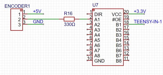
For digital inputs, sometimes using a resistive divider can work, for slow speed inputs. If you want to reliably drive a Teensy input, the voltage MUST be between 0V and 3.3V at all times. Resistive dividers can slow down or retard rise times of signals, depending on your load capacitance. There is a whole thread on voltage translation - in the Technical Support Forum, I suggest you read it. There is a lot of information there, and you can learn about the pluses and minuses of different approaches. Personally, I have used a 74LVT245 device for a buffered input to the Teensy. I run my encoders through the 245 device. The 74LVT245 can drive +/-24mA. The inputs are +5V tolerant, even though Vcc=+3.3V. This means, the 74LVT245 can receive a 0-5V signal and translate it to a 0-3.3V signal. I am sure there are other devices, perhaps even better, cheaper or faster. A 74LVT245 device works fine for my application, using a spindle rotary encoder and DRO read heads.

This advice is being given to avoid you some heartache. If you connect your Teensy 4.1 to 5V devices directly, your Teensy will be damaged and may fail completely. Please read the Teensy 4.1 product page word for word. There is very good, valuable and essential information on that page. It's how I started to learn about Teensy's. Good luck with your endeavor.
 
Thanks Clinker8, I really appreciate the help.

I have purchased some of the transistors and resistors you specified above.

One last thing, are you able to explain how you selected the 2000 ohm resistor?

Thanks!
 
Post #7 explains the calculations. 2k gives about 1mA current in the transistor. The 1mA is sourced from the Teensy4.1, which is a safe level for the Teensy.
 
AHCT parts might work, although they are not guaranteed to do so. You need to use Vcc = 3.3V, and that voltage is not within the recommended voltage range, according to the datasheet. The datasheet also does not state the inputs are +5V tolerant. If your part is used outside of the recommended range, you cannot expect to part to work correctly.

An LVT family part is 5V tolerant when operating at Vcc=3.3V. The datasheet says it can be used for voltage translation. In my opinion, the LVT family of parts is a better choice. There may be other logic families that are good, but I have not found them yet.
 
Thanks, I will look into them as well.

I am in the process of designing my custom PCB.

For Input's EG buttons, limit switches, probes, etc. Should i have anything in series, or is it okay to run Teensy Pin -> Switch <- Ground?

Cheers
 
You should be ok. You will need to remember to set the Teensy internal pull ups, or the Teensy will not read the switches reliably. Use pinMode with the INPUT_PULLUP setting. This is for slowly changing signals, like mechanical switches. For fast changing inputs, like a rotary encoder, a stronger pull up resistor to +3.3V is required. I chose 330 ohms on the output of my rotary encoder, because the input frequency could be as high as 400kHz.

Higher values of resistance will have longer rise times. These rise times can affect the maximum frequency that the pin can read. Longer rise times can also cause false triggering. You may need to experiment with resistance values. When I had 2k pull ups, my rotary encoder was not sensed correctly. 330 ohms made the Teensy reliably read it. In full disclosure, I used a 74LVT245 as a level translator. The encoder was pulled up to +5V and this signal was connected to the 74LVT245. The output of the 245 buffer (now at 3.3V levels) was connected to the Teensy. The LVT245 has nice clean sharp and fast rise and fall times. For me, this has been a reliable input to the Teensy.
 
Thanks, Clinker.
Is this how you have the input wired?
Quite confusing with all these different parts.
xX0hSx7
 

Attachments

  • WIRING2.PNG
    WIRING2.PNG
    71.5 KB · Views: 36
You need to read the data sheets of the parts to study how to use them. That takes a little time. At this point, you have used up my patience and most of my good will. I will not continue to spoon feed you with answers to every single little question. Perhaps this is not a good endeavor for you. Or maybe you are just starting out. If you are just starting out, it takes a while to become proficient. My best advice, read the data sheets! They usually tell you how to use the parts. If you cannot understand the datasheets, ask specific questions and people can help you. But please, don't ask us to do your designs. That is your responsibility, not ours. Designs require work - by you.

For the record, the picture in post #18 above is totally wrong in several ways. A pull up resistor pulls up to a voltage. In this case, to 5V. That is not explicitly shown in your diagram. ENC1-pin 2 should be directly wired to U7 - pin 2, One end of R16 should be connected to +5V. The other end of R16 should be connected to U7 - pin 2. Second, you have not turned on the output enable, nor have you set the direction, so the part will not work as you expect. Read the datasheet and follow the recommendations, usually found in the test section. I am bowing out from this discussion. Please do not contact me via PM, I will ignore you. Wish you continued success in your project.
 
Back
Top