Teensy used as a DSP ?

Hi,

I am an experienced Arduino user but I am a beginner with Teensy, as I have not yet used a Teensy board.

I have this project on my table, and I need your expertise to know of it is possible (recommanded) to achieve it using a Teensy 4.1 (maybe Teensy 4.1 is not powerful enough and I should use a more DSP oriented chip ?).

My project is to used a Teensy 4.1 as a DSP, that will perform a F.I.R. filter prior a DAC.
Please find attached a quick diagram of what I would like to achieve.

DSP with Teensy.JPG

Do you know if somebody has already achieved a similar project starting from a SPDIF input and going to an external audio DAC ?

Do you have any examples of a SPDIF / DSP / DAC project ?

Thank you very much for your help,
 
Start with the audio library tutorial.

https://www.pjrc.com/store/audio_tutorial_kit.html

Maybe skip past section 1 and go right to using the design tool. There's also a full walkthrough video if you'd prefer to watch & listen rather than read.

The audio library has a lot of features not covered in the tutorial, but hopefully once you understand how it works you can discover them pretty easily in the design tool.

Teensy 4.1 has a SPDIF receiver built in, so you'll only need an optical receiver. The audio library has FIR and other filter types. You'll probably want to use I2S output to feed a good quality DAC.
 
Thanks friends, so I have walked through the Audio Tutorial and Audio Design Tool for Teensy (but not only, see below).
The Audio Tutorial is not a problem (even if my project is almost exclusively in the digital domain, prior the DAC conversion and playing the files)

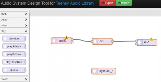
I have designed the attached flowchart,
flow chart 01.JPG

because my project is to use a SPDIF input and a I2S output (or anything else that could feed an audio DAC chip) with a FIR Filter in between (phase linear required):

Code:
//Generated y the Audio Design Tool with: SPDIF Input -> FIR -> I2S Output

#include <Audio.h>
#include <Wire.h>
#include <SPI.h>
#include <SD.h>
#include <SerialFlash.h>

// GUItool: begin automatically generated code
AudioInputSPDIF3         spdif3_1;       //xy=155.25,118.25
AudioFilterFIR           fir1;           //xy=353.25,121.25
AudioOutputI2S           i2s1;           //xy=569.25,126.25
AudioConnection          patchCord1(spdif3_1, 0, fir1, 0);
AudioConnection          patchCord2(fir1, 0, i2s1, 0);
AudioControlSGTL5000     sgtl5000_1;     //xy=360.25,265.25
// GUItool: end automatically generated code

I am unable to say if this code is correct (?) nor if my flowchart is OK...

Obviously the specifications of the FIR filter are missing, and I have spent my afternoon to try to sort out how to define a FIR, but I propose to talk about this later on.

The first thing I need to know is: what should I add to this code to make it running and test it ?

Thank you very much,
 
Those yellow error triangles mean you have used inputs and output which can not work together. Usually this means they have incompatible audio clocking requirements.

Try spdif_async rather than spdif, if you will be sending the output to i2s which is synchronous to Teensy's clock.

You can also see the documentation (on the right side panel) for each item by clicking on it. Details about how each works and special notes about compatibility with others are usually mentioned in that documentation.
 
Try spdif_async rather than spdif, if you will be sending the output to i2s which is synchronous to Teensy's clock.

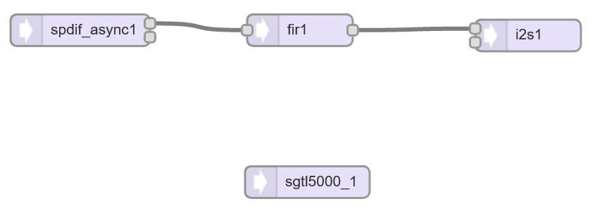
Perfect: I understand the Clock incompatibility that you explain, and I have modified the diagram in the Audio Design Tool according to your recommendation:

diagramme rentré dans Audio System Design Tool.JPG

and here is the code that has been generated:
Code:
#include <Audio.h>
#include <Wire.h>
#include <SPI.h>
#include <SD.h>
#include <SerialFlash.h>

// GUItool: begin automatically generated code
AsyncAudioInputSPDIF3    spdif_async1;   //xy=145.3333282470703,121.33333587646484
AudioFilterFIR           fir1;           //xy=353.25,121.25
AudioOutputI2S           i2s1;           //xy=569.25,126.25
AudioConnection          patchCord1(spdif_async1, 0, fir1, 0);
AudioConnection          patchCord2(fir1, 0, i2s1, 0);
AudioControlSGTL5000     sgtl5000_1;     //xy=360.25,265.25
// GUItool: end automatically generated code

So if we assume that this code is correct, the most critical remaining part relates to the FIR filter.

I went to T-Filter to get the coefficients of a Low-Pass filter (we will optimize them later) but assuming that they are correct, how should I proceed to define this Low Pass filter into this sketch ??

I see
"AudioFilterFIR fir1; //xy=353.25,121.25"
in the code, but it has to be modified with the coefficients calculated by T-Filter.

How to do this ?

Thank you very much,
 
Back
Top