stepper forward/reverse switch

edrummer

Well-known member
I need to connect a 3 position momentary toggle switch to run a stepper motor in either forward or reverse. I have a TB600 driver and a NEMA23 stepper bipolar motor and a teensy 3.2 board. I'm not sure how to wire it or if this code will work, I can't seam to find a good example of this. Any help would be appreciated.
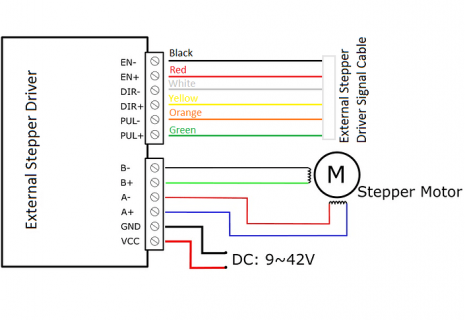
Code:
const int stepPin = 5; 
const int dirPin = 2; 
const int enPin = 8;

void setup() {
  pinMode(stepPin,OUTPUT); 

  pinMode(dirPin,OUTPUT);
  pinMode(enPin,OUTPUT);
  digitalWrite(enPin,LOW);
  
}

void loop() {
  digitalWrite(dirPin,HIGH); // Enables the motor to move in a particular direction
  for(int x = 0; x < 800; x++) {
    digitalWrite(stepPin,HIGH); 
    delayMicroseconds(500); 
    digitalWrite(stepPin,LOW); 
    delayMicroseconds(500); 
  }
  delay(1000); // One second delay
  digitalWrite(dirPin,LOW); //Changes the direction of rotation
  for(int x = 0; x < 800; x++) {
    digitalWrite(stepPin,HIGH);
    delayMicroseconds(500);
    digitalWrite(stepPin,LOW);
    delayMicroseconds(500);
  }
  delay(1000); 
}
b7c17db043ee1be832f26bee7b503c23db331a60_2_690x475.png
 
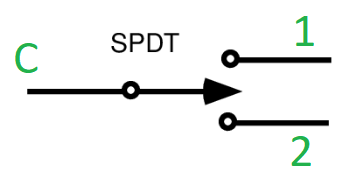
Assuming your toggle switch is electrically like this [with neutral position]:
SPDT with neutral pos.PNG

If so, connect C to GND, 1 to Teensy pin 3 and 2 to Teensy pin 4. Then try the code below. BOLD is added code.

Code:
const int stepPin = 5;
const int dirPin = 2;
const int enPin = 8;

[B]const int SW1pin = 3; // switch C pin connects to GND
const int SW2pin = 4;
volatile bool dirLR = LOW;[/B]

void setup() {
[B]  pinMode(SW1pin, INPUT_PULLUP);
  pinMode(SW2pin, INPUT_PULLUP);
  attachInterrupt(digitalPinToInterrupt(SW1pin), switch_to_left, FALLING);
  attachInterrupt(digitalPinToInterrupt(SW2pin), switch_to_right, FALLING);[/B]
  
  pinMode(stepPin, OUTPUT);
[B]  digitalWrite(stepPin, LOW);[/B]
  pinMode(dirPin, OUTPUT);
[B]  digitalWrite(dirPin, LOW);[/B]
  pinMode(enPin, OUTPUT);
  digitalWrite(enPin, LOW);
}

void loop() {
  digitalWrite(dirPin, [B]dirLR[/B]); 
  for (int x = 0; x < 800; x++) {
    digitalWrite(stepPin, HIGH);
    delayMicroseconds(500);
    digitalWrite(stepPin, LOW);
    delayMicroseconds(500);
  }
  delay(1000); // One second delay
}

[B]void switch_to_left() {
    dirLR = HIGH;
}

void switch_to_right() {
    dirLR = LOW;
}[/B]

The code compiles fine but I did not actually test it on real hardware...
Paul
 
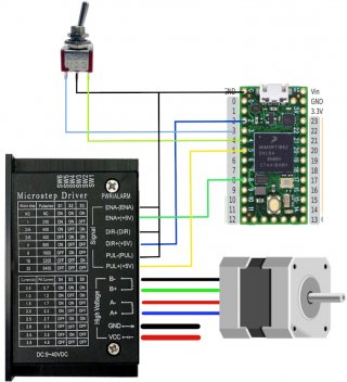
is this the correct wiring?
Looks OK, you have the controller connected in Common-Cathode mode [according to this spec].

What I'm a bit worried about is whether the output voltage of the Teensy (being 3V3 max) is enough to drive the stepper motor driver. The spec only mentions 5V or higher.
However, on this page, it states "Control Signal: 3.3~24V". So your milage may vary.

On your question "Is there a way to adjust the speed in this code?". Yes, there is. Just play with the delay values here:
Code:
  for (int x = 0; x < 800; x++) {
    digitalWrite(stepPin, HIGH);
    delayMicroseconds([COLOR="#FF0000"]500[/COLOR]);
    digitalWrite(stepPin, LOW);
    delayMicroseconds([COLOR="#FF0000"]500[/COLOR]);
  }

But if you want more control about the stepper, consider using the very useful TeensyStep library. The author of the library is an active and supportive member on this forum.

Paul
 
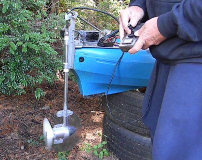
Thank's Paul, I really appreciate your help. I looked at the library, I really don't know much about this. The motor turns an actuator which lifts the prop up and down for a trolling motor I built for my kayak. I had it working for a few years now but the switch has always been problomatic. The code I used was for one axis of a joystick which worked the same as a toggle only with variable speed. I didn't need variable speed
but I couldn't use a toggle switch with that code even with resistors and I don't know how to change it. When this switch went bad again, I decided to try and fix it right so I can use a small waterproof toggle switch. TM.jpgThis is the code, it's the same one I used for the steering motor, it is connected common anode to the TB6600. I don't know if it's possable to change the code so that it can use the toggle switch.
Code:
[code]

#include <AccelStepper.h> // accelstepper library
AccelStepper stepper(1, 8, 9); // direction Digital 9 (CCW), pulses Digital 8 (CLK)

//Pins
const byte Analog_X_pin = A1; // x-axis readings
const byte enablePin = 7;

//Variables
int Analog_X = 0;             //x-axis value
int Analog_X_AVG = 0;         //x-axis value average
  //---------------------------------------------------------------------------- 
void setup() {
  Serial.begin(9600);
  //----------------------------------------------------------------------------    
  //PINS
  pinMode(Analog_X_pin, INPUT);
  pinMode(enablePin, OUTPUT);
  pinMode(2, INPUT_PULLUP); 
  pinMode(3, INPUT_PULLUP);
  //----------------------------------------------------------------------------  
  InitialValues(); // averaging the values of analog pin 0 (value from potmeter)
  //----------------------------------------------------------------------------  
  // Stepper parameters
  // setting up some default values for maximum speed and maximum acceleration
  stepper.setMaxSpeed(2000);     //SPEED = Steps / second  
  stepper.setAcceleration(1000); //ACCELERATION = Steps /(second)^2    
  stepper.setSpeed(1000);
  delay(1000);
}

void loop()
{
  ReadAnalog();
  ReadLimits();  
  stepper.runSpeed(); //step the motor (this will step the motor by 1 step at each loop indefinitely)
}

void ReadLimits()
{
  if( digitalRead(2)==LOW && stepper.speed()>0 )//read input, assuming they have pull-up resistors.
  {
    stepper.setSpeed(0);
  }

  if( digitalRead(3)==LOW && stepper.speed()<0 )//read input, assuming they have pull-up resistors.
  {
    stepper.setSpeed(0);
  }
}

void ReadAnalog() {
  if (abs(Analog_X-Analog_X_AVG) > 50) {
    digitalWrite(enablePin, HIGH);  // enable the driver
    stepper.setSpeed(5*(Analog_X-Analog_X_AVG));   
  } else {
    digitalWrite(enablePin, LOW);   // disable the driver
    stepper.setSpeed(0);
  }
  // Reading the potentiometer in the joystick: 
  Analog_X = analogRead(Analog_X_pin);  
  // if the value is 25 "value away" from the average (midpoint), we allow the update of the speed
  // This is a sort of a filter for the inaccuracy of the reading
  if (abs(Analog_X-Analog_X_AVG) > 50) {
    stepper.setSpeed(5 * (Analog_X-Analog_X_AVG));    
  } else {
    stepper.setSpeed(0);
  }
}

void InitialValues() {
  //Set the values to zero before averaging
  float tempX = 0;
  //----------------------------------------------------------------------------  
  // read the analog 50x, then calculate an average. 
  // they will be the reference values
  for (int i = 0; i<50; i++) {
    tempX += analogRead(Analog_X_pin);  
    delay(10); //allowing a little time between two readings
  }
  //----------------------------------------------------------------------------  
  Analog_X_AVG = tempX/50; 
  //----------------------------------------------------------------------------  
  Serial.print("AVG_X: ");
  Serial.println(Analog_X_AVG);
  Serial.println("Calibration finished");  
}
[/CODE]
 
Thanks for showing your application.
If your required functionality is like this:
- as long as the switch is in position 1 (let's say up) the stepper motor turns such that the prop goes up, or,
- as long as the switch is in position 2 (let's say down) the stepper motor turns such that the prop goes down, or,
- as long as the switch is in the neutral position then the stepper motor should do nothing.
then the code should be fairly simple:
Code:
#define stepPin 5
#define dirPin 2
#define enPin 8
#define SW1pin 3                      // switch C pin connects to GND
#define SW2pin 4
int uSeconds = 500;                   // adjust this value to vary the motor speed

void setup() {
  pinMode(SW1pin, INPUT_PULLUP);
  pinMode(SW2pin, INPUT_PULLUP);

  pinMode(stepPin, OUTPUT);
  digitalWrite(stepPin, LOW);
  pinMode(dirPin, OUTPUT);
  digitalWrite(dirPin, LOW);
  pinMode(enPin, OUTPUT);
  digitalWrite(enPin, LOW);
}

void loop() {
  while (digitalRead(SW1pin) == LOW) {  // while switch is in up position, send step pulses
    digitalWrite(dirPin, LOW);          // set up direction
    digitalWrite(stepPin, HIGH);
    delayMicroseconds(uSeconds);
    digitalWrite(stepPin, LOW);
    delayMicroseconds(uSeconds);
  }
  while (digitalRead(SW2pin) == LOW) {  // while switch is in down position, send step pulses
    digitalWrite(dirPin, HIGH);         // set down direction
    digitalWrite(stepPin, HIGH);
    delayMicroseconds(uSeconds);
    digitalWrite(stepPin, LOW);
    delayMicroseconds(uSeconds);
  }
  delay(10);                            // scan switch inputs every 10ms
}

With respect to the TB6600 stepper motor driver: it's quite bulky. A smaller DRV8825 will drive a NEMA23 as well.

Paul
 
Yes that is exactly how it works. There are 2 end switches (I used hall sesors) in the origional code that turn the motor off when it reaches fully up or down. I tried using the dvr8825 drivers first but kept burning them up. Maybe not big enough heat sink. Thats why I went to the TB6600. I'm using a 24v battery, I don't know how many amps that motor is drawing but I suspect a fair amount for a short time. Anyway I have the drivers in a waterproof box with the heat sink on the outside and that has worked fine. I just need to replace the switch. I ordered a toggle switch, should be this here this week, then I can try the code. If it works then I just need to add the end switches. Thanks again.
 
Last edited:
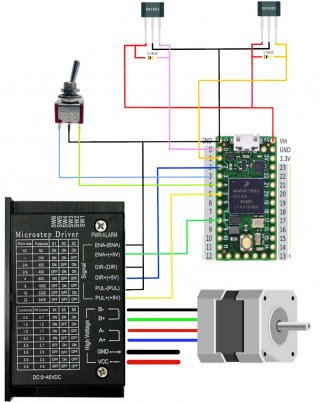
I finally got to try this code for the toggle switch, it worked great! I haven't adjusted the speed yet, and I need to add these end switches. There are 2 hall sensors that should stop the motor when it reaches either end. I have a magnet on the assembly and when it gets close enough to the sensor it stops the motor from going any farther in that direction, but can still go back in the other direction, I thought I could just copy from the old code but I'm not sure I can because that one was wired common anode. Could you look at the code and tell me if it should work?

Code:
#define stepPin 5
#define dirPin 2
#define enPin 8
#define SW1pin 3                      // switch C pin connects to GND
#define SW2pin 4
int uSeconds = 500;                   // adjust this value to vary the motor speed

void setup() {
  pinMode(SW1pin, INPUT_PULLUP);
  pinMode(SW2pin, INPUT_PULLUP);

  pinMode(stepPin, OUTPUT);
  digitalWrite(stepPin, LOW);
  pinMode(dirPin, OUTPUT);
  digitalWrite(dirPin, LOW);
  pinMode(enPin, OUTPUT);
  digitalWrite(enPin, LOW);

  pinMode(Analog_X_pin, INPUT);
  pinMode(enablePin, OUTPUT);
  pinMode(0, INPUT_PULLUP); 
  pinMode(1, INPUT_PULLUP);
}

void loop() {
  while (digitalRead(SW1pin) == LOW) {  // while switch is in up position, send step pulses
    digitalWrite(dirPin, LOW);          // set up direction
    digitalWrite(stepPin, HIGH);
    delayMicroseconds(uSeconds);
    digitalWrite(stepPin, LOW);
    delayMicroseconds(uSeconds);
  }
  while (digitalRead(SW2pin) == LOW) {  // while switch is in down position, send step pulses
    digitalWrite(dirPin, HIGH);         // set down direction
    digitalWrite(stepPin, HIGH);
    delayMicroseconds(uSeconds);
    digitalWrite(stepPin, LOW);
    delayMicroseconds(uSeconds);
  }
  delay(10);                            // scan switch inputs every 10ms
  void ReadLimits()
{
  if( digitalRead(0)==LOW && stepper.speed()>0 )//read input, assuming they have pull-up resistors.
  {
    stepper.setSpeed(0);
  }

  if( digitalRead(1)==LOW && stepper.speed()<0 )//read input, assuming they have pull-up resistors.
  {
    stepper.setSpeed(0);
  }
}
}

teensy toggle.jpg
 
Caution: since a Teensy 4.0 is NOT 5V tolerant, you should not pullup the outputs of the US1881 hall-sensors with that 10K resistor to the 5V. I hope your Teensy is still OK...
Please remove the 10K resistors; we will use the internal pullups of pins 0 & 1. You need to power the hallsensor by 5V though.

Now to your code. I tried to compile it but it fails. Not sure why you wanted to use stepper library - we will generate all the required signals ourselves without the use of a library.
Also got rid of the ReadLimits() function. Reading of the hallsensors is done also when reading the switches.
Code:
#define stepPin 5
#define dirPin 2
#define enPin 8
#define SW1pin 3                      // switch C pin connects to GND
#define SW2pin 4
#define hallsensor1Pin 0              // connect first hallsensor to pin 0
#define hallsensor2Pin 1              // connect second hallsensor to pin 1
int uSeconds = 500;                   // adjust this value to vary the motor speed

void setup() {
  pinMode(SW1pin, INPUT_PULLUP);
  pinMode(SW2pin, INPUT_PULLUP);
  pinMode(hallsensor1Pin, INPUT_PULLUP);
  pinMode(hallsensor2Pin, INPUT_PULLUP);

  pinMode(stepPin, OUTPUT);
  digitalWrite(stepPin, LOW);
  pinMode(dirPin, OUTPUT);
  digitalWrite(dirPin, LOW);
  pinMode(enPin, OUTPUT);
  digitalWrite(enPin, LOW);
}

void loop() {
  while (digitalRead(SW1pin) == LOW && digitalRead(hallsensor1Pin) == LOW) {  // while switch is in up position AND hallsensor1 is not activated, send step pulses
    digitalWrite(dirPin, LOW);          // set up direction
    digitalWrite(stepPin, HIGH);
    delayMicroseconds(uSeconds);
    digitalWrite(stepPin, LOW);
    delayMicroseconds(uSeconds);
  }
  while (digitalRead(SW2pin) == LOW && digitalRead(hallsensor2Pin) == LOW) {  // while switch is in down position AND hallsensor2 is not activated, send step pulses
    digitalWrite(dirPin, HIGH);         // set down direction
    digitalWrite(stepPin, HIGH);
    delayMicroseconds(uSeconds);
    digitalWrite(stepPin, LOW);
    delayMicroseconds(uSeconds);
  }
  delay(10);                            // scan switch inputs every 10ms
}

According the hall-sensor datasheet, the sensor needs a reverse in magnet polarity to switch from HIGH to LOW or viceversa. This is a so-called latching switch. So it does not behave like 'normal' hall-sensor as in 'no magnet' means output LOW, 'magnet present' means output HIGH. You may want to search for another hall-sensor. Or just a reed switch.

But do you need the hall-sensors at all? I mean, you operate the switch manually up or down, so why not set the switch to the neutral position manually when the prop is at the desired position? Less parts is more reliable...

Paul
 
I'm sorry I just used a photo I found of the hall sensor, those are not the ones I used, I believe I used unipolar sensors they were not latching, they just kept the motor from running in that direction when in the presence of the magnetic field. when the field moved away it became active again. I would like to keep these for several reasons. I had issues with the old switch (pot) it would come on by it self sometimes I hope the toggle will fix that but I like the fact that I can hit the switch and know that it will shut off when fully up or down. I use it in the ocean and when I first go in or out I'm in the surf with a lot going on so I'd really like to keep these and the have worked well. I was hoping to be able to add condition to the code something like-
while (digitalRead(SW1pin) == LOW && digitalRead(hallsensor1Pin) == LOW) { // while switch is in up position AND hallsensor1 is not activated, send step pulses
digitalWrite(dirPin, LOW); // set up direction
honestly I don't know how to do that. This is how it was in the old code but it was wired common anode.
 
I'm sorry I just used a photo I found of the hall sensor, those are not the ones I used
Ah OK, just be aware to hook up the actual sensor correctly. Do you have a datasheet or part# of the actual hall-sensor?

I was hoping to be able to add condition to the code
Well, that is exactly what I did by adding the red condition:
Code:
while (digitalRead(SW1pin) == LOW [COLOR="#FF0000"]&& digitalRead(hallsensor1Pin) == LOW[/COLOR]) {
Meaning both the switch must be active/LOW and the hall-sensor must be inactive/LOW. If one or both conditions are not true, then the while loop is exited and the motor isn't stepped.
But I maybe I misunderstand you.

the old code but it was wired common anode
This has to do with how the controller is connected, nothing to do with the hall-sensors and/or switches.

Paul
 
Thankyou, I have to do some digging for the sensors, this was a few years ago and they are covered up so I can't get the numbers, but I'll look, (may take a while)
 
After watching the video, it is my understanding now that the Teensy will not only tilt the prop but also read the joystick and drive the propmotor and steer left & right. Is that correct?
If so, you may want to share the complete code to have a look at. Now I understand where pinMode(Analog_X_pin, INPUT); came from...

Are you using a Teensy 3.2 or Teensy 4.0? [wiring diagram shows a Teensy 4.0]

Paul
 
Thanks Paul, I'm happy to share anything I have but in the origional set up I used 2 nanos because they use 5v. I got the code from a youtube video and modified it (with some help) you may have guessed I have little to no experiance in coding. I tried to combine the codes and just use one board but I had problems and it was just easier to use 2 boards. They have failed several times, and I had a tennsy 3.2 and a 3.6 left over from another project, so I thought I could use one for the lift motor. I still use the other board for the steering and drive motors but this one has always been a problem. I may have used the wrong board for the illistration but it's a 3.2. If this turns out to be reliable, I can put the other motors on this board also, but for now I just need to get it back up and running again. I won't be able to work on it for a few days, I will keep you posted Thanks again
 
Thanks for letting me know the hall-sensor.
According to the datasheet the open collector output goes LOW when a magnet is closing in. And HIGH when the magnet moves away.
So that needs a small change in my code from message #10. Here is the updated code:
Code:
#define stepPin 5
#define dirPin 2
#define enPin 8
#define SW1pin 3                      // switch C pin connects to GND
#define SW2pin 4
#define hallsensor1Pin 0              // connect first hallsensor to pin 0
#define hallsensor2Pin 1              // connect second hallsensor to pin 1
int uSeconds = 500;                   // adjust this value to vary the motor speed

void setup() {
  pinMode(SW1pin, INPUT_PULLUP);
  pinMode(SW2pin, INPUT_PULLUP);
  pinMode(hallsensor1Pin, INPUT_PULLUP);
  pinMode(hallsensor2Pin, INPUT_PULLUP);

  pinMode(stepPin, OUTPUT);
  digitalWrite(stepPin, LOW);
  pinMode(dirPin, OUTPUT);
  digitalWrite(dirPin, LOW);
  pinMode(enPin, OUTPUT);
  digitalWrite(enPin, LOW);
}

void loop() {
  while (digitalRead(SW1pin) == LOW && digitalRead(hallsensor1Pin) == [COLOR="#FF0000"]HIGH[/COLOR]) {  // while switch is in up position AND hallsensor1 is not activated, send step pulses
    digitalWrite(dirPin, LOW);          // set up direction
    digitalWrite(stepPin, HIGH);
    delayMicroseconds(uSeconds);
    digitalWrite(stepPin, LOW);
    delayMicroseconds(uSeconds);
  }
  while (digitalRead(SW2pin) == LOW && digitalRead(hallsensor2Pin) == [COLOR="#FF0000"]HIGH[/COLOR]) {  // while switch is in down position AND hallsensor2 is not activated, send step pulses
    digitalWrite(dirPin, HIGH);         // set down direction
    digitalWrite(stepPin, HIGH);
    delayMicroseconds(uSeconds);
    digitalWrite(stepPin, LOW);
    delayMicroseconds(uSeconds);
  }
  delay(10);                            // scan switch inputs every 10ms

Again, don't mount the 10K pullup resistors, Teensy INPUT_PULLUP will take care of that. For the rest the wiring diagram of your message #9 should be OK to tilt the prop using the 3-way switch and the hall-senors.

Paul
 
I was able to connect the hall switches this weekend, The code works perfectly, just one thing I forgot to mention. In the origional code the motor was completely off when idle. Because I'm using a battery and don't need holding current. If you could show me how to do that I'd really appreciate it. Thanks again for all your help.
 
The Enable signal [active low] of the TB6600 is used for this purpose. When the Enable pin is high, the motor driver is not enabled and thus the motor is not driven.
So in setup() the driver is default disabled. Only in the while{} loop, the motor driver is enabled.
Here is the code:
Code:
#define stepPin 5
#define dirPin 2
#define enPin 8
#define SW1pin 3                      // switch C pin connects to GND
#define SW2pin 4
#define hallsensor1Pin 0              // connect first hallsensor to pin 0
#define hallsensor2Pin 1              // connect second hallsensor to pin 1
int uSeconds = 500;                   // adjust this value to vary the motor speed

void setup() {
  pinMode(SW1pin, INPUT_PULLUP);
  pinMode(SW2pin, INPUT_PULLUP);
  pinMode(hallsensor1Pin, INPUT_PULLUP);
  pinMode(hallsensor2Pin, INPUT_PULLUP);

  pinMode(stepPin, OUTPUT);
  digitalWrite(stepPin, LOW);
  pinMode(dirPin, OUTPUT);
  digitalWrite(dirPin, LOW);
  pinMode(enPin, OUTPUT);
  [COLOR="#FF0000"]digitalWrite(enPin, HIGH);          // disable driver[/COLOR]
}

void loop() {
  while (digitalRead(SW1pin) == LOW && digitalRead(hallsensor1Pin) == HIGH) {  // while switch is in up position AND hallsensor1 is not activated, send step pulses
    [COLOR="#FF0000"]digitalWrite(enPin, LOW);           // enable driver[/COLOR]
    digitalWrite(dirPin, LOW);          // set up direction
    digitalWrite(stepPin, HIGH);
    delayMicroseconds(uSeconds);
    digitalWrite(stepPin, LOW);
    delayMicroseconds(uSeconds);
  }
  while (digitalRead(SW2pin) == LOW && digitalRead(hallsensor2Pin) == HIGH) {  // while switch is in down position AND hallsensor2 is not activated, send step pulses
    [COLOR="#FF0000"]digitalWrite(enPin, LOW);           // enable driver[/COLOR]
    digitalWrite(dirPin, HIGH);         // set down direction
    digitalWrite(stepPin, HIGH);
    delayMicroseconds(uSeconds);
    digitalWrite(stepPin, LOW);
    delayMicroseconds(uSeconds);
  }
  delay(10);                            // scan switch inputs every 10ms
  [COLOR="#FF0000"]digitalWrite(enPin, HIGH);            // disable driver[/COLOR]
}

Hope this helps,
Paul
 
Back
Top