QSPI pull-up resistors required?

The NXP reference design shows pull up resistors on the /WP and /RESET and /CE signals on the QSPI flash but the Teensy 4.1 design doesn't have those pull ups. The NXP FAE is saying it needs them for sure (but just during the initial startup for the 30MHz access of flash).

Does that sound right? I thought the pins default to weak pull up (100k)?

edit: This is for Teensy 4.1
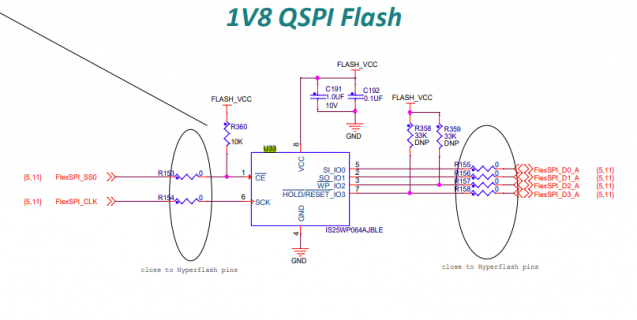
QSPI_FLASH.png
 
Looking at just the image, R153 to R158 are all zero-ohm links, not resistors per se; and R358 and R359 are DNP, Do Not Populate.
In other words, the only pull-up resistor I see is R360, 10kOhm from /CE to VCC.
 
Ah, I hate it when I'm not clear. That is a snip from the reference schematic (the demo board). The instructions in the text clearly state to remove the zero ohm jumpers from the hyperflash (not shown) and add the zero ohm jumpers on the QSPI. They also say to add the pull ups.

edit: There is text in the schematic that doesn't talk about the pull-ups (it doesn't say one way or the other) but the text in the manual says it. I hate inconsistent stuff like this. FAE says you need them.
 
Last edited:
Back
Top