Hi, I am a car guy with some Arduino experience. I love making small projects with the Arduinos, but most of my projects a copied from others and modified to suit. Same applies to my new project, but this one is more complicated and; Teensy based. The choice for Teensy is based on the fact that on the current Speeduino firmware, it can support CANbus communication. I also believe it is best to stick with the 3.5, as it is 5V tolerant.
A bit of background on the why and how. The CANbus communication is a wish, but not the only reason to chose this project. My car's setup (1998 MX-5 with a 2004 MX-5 1.8 VVT engine and turbo) has evolved over the past few years. I started with a simple Speeduino 0.4.4 board on an Arduino Mega, as it should. I have a third PCB I made myself (JLCPCB) between the 40 pin Speeduino connector and the 73 pin Mazda connector. On that board is an IC converting some outputs from 5 to 12V and higher power, to control actuators on the engine. I also added a few extra outputs on another PCB, for some more high power outputs not coming from the 40 pin Speeduino output. There is another PCB (fourth, are you counting) floating somewhere in the wiring harness, controlling my alternator for stable voltage. The fifth board is also floating in the wiring harness, and converts the wideband O2 sensor signal to 0 - 5V and powers the sensor heater. To convert this set-up to Teensy 3.5 calls for another PCB, housing the Teensy, and mimicking the Mega (with signal converters on it). That would be the 6th PCB. And a lot of messy wiring and unnecessary parts. So, I want one 'motherboard' with as much on it as possible, and nothing more. The Teensy will be mounted to that board and so will the wideband sensor controller, as I have not been able to reverse engineer it (as I did with the alternator controller).
But, as I said in the beginning, I don't really know what I am doing. And I want to learn. I hope to get some help here. So, here are some questions:
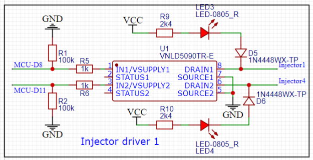
For various outputs, grounding things like injectors (on/off coil), idle control valve (PWM coil) boost control valve (PWM coil), etc, the schematic I found is this:

I think I copied this from a Teensy based Speeduino board, but I cannot guarantee it. How to I detemine this IC and the Teensy are happily working together, right voltages (3,3V) and currents?
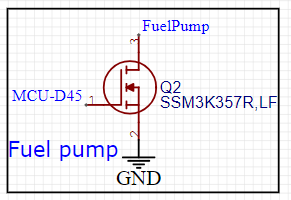
Besides that, two other high current outputs (fuel pump and cooling fan, both switchting the ground of a relais) are drawn like this:

First, again the same question, is this working with the Teensy, and how do I know? But even more of a question to me is why use two different set-ups for high current grounding outputs? Why use two of the above for fuel pump relais and cooling fan relais, and not one of the first schematic to run both?
I also have a lot of questions about inputs, but with the above clear I can finish up the outputs, first. Oh, if anyone here can let me know how I can link to an EasyEDA project, live, please let me know. I can then give you all access to my whole project.
Any help is appreciated, if you need advice on turboing your car let me know
Cheers,
Hugo
A bit of background on the why and how. The CANbus communication is a wish, but not the only reason to chose this project. My car's setup (1998 MX-5 with a 2004 MX-5 1.8 VVT engine and turbo) has evolved over the past few years. I started with a simple Speeduino 0.4.4 board on an Arduino Mega, as it should. I have a third PCB I made myself (JLCPCB) between the 40 pin Speeduino connector and the 73 pin Mazda connector. On that board is an IC converting some outputs from 5 to 12V and higher power, to control actuators on the engine. I also added a few extra outputs on another PCB, for some more high power outputs not coming from the 40 pin Speeduino output. There is another PCB (fourth, are you counting) floating somewhere in the wiring harness, controlling my alternator for stable voltage. The fifth board is also floating in the wiring harness, and converts the wideband O2 sensor signal to 0 - 5V and powers the sensor heater. To convert this set-up to Teensy 3.5 calls for another PCB, housing the Teensy, and mimicking the Mega (with signal converters on it). That would be the 6th PCB. And a lot of messy wiring and unnecessary parts. So, I want one 'motherboard' with as much on it as possible, and nothing more. The Teensy will be mounted to that board and so will the wideband sensor controller, as I have not been able to reverse engineer it (as I did with the alternator controller).
But, as I said in the beginning, I don't really know what I am doing. And I want to learn. I hope to get some help here. So, here are some questions:
For various outputs, grounding things like injectors (on/off coil), idle control valve (PWM coil) boost control valve (PWM coil), etc, the schematic I found is this:

I think I copied this from a Teensy based Speeduino board, but I cannot guarantee it. How to I detemine this IC and the Teensy are happily working together, right voltages (3,3V) and currents?
Besides that, two other high current outputs (fuel pump and cooling fan, both switchting the ground of a relais) are drawn like this:

First, again the same question, is this working with the Teensy, and how do I know? But even more of a question to me is why use two different set-ups for high current grounding outputs? Why use two of the above for fuel pump relais and cooling fan relais, and not one of the first schematic to run both?
I also have a lot of questions about inputs, but with the above clear I can finish up the outputs, first. Oh, if anyone here can let me know how I can link to an EasyEDA project, live, please let me know. I can then give you all access to my whole project.
Any help is appreciated, if you need advice on turboing your car let me know
Cheers,
Hugo

